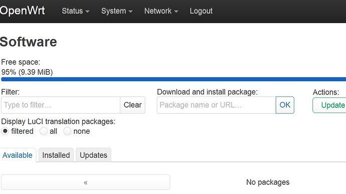
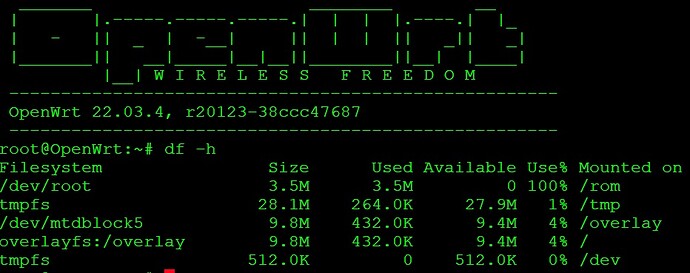
I'm thinking of replacing the spi flash of my tplink archer c20 v5 which is currently 8 MB with a 16 MB one, so I'm trying to create a suitable firmware and to do so I'm using the image-builder tool but I can't find the definitions to be changed relating to flash layout (8MSUmtk), can anyone who has already done it give me a hand?
You will need to compile from source to enable the use of 16MB of flash memory.
This type of physical modification is rarely worth it as it involves purchasing a SPI flash chip and a programmer, and then riskig physical damage to the device during the soldering operations. Yes, it's true that the chips and programmers aren't that expensive, but that money is almost always better spent on newer, more capable hardware. This is especially true when you consider the rest of the specs of the device (5x 100Mbps ports, 580MHz MT7628NN SoC, 64MB RAM, and a 433Mbps theoretical max bandwidth on the 5G radio).... it's still functional and you can run 23.05, but it's old and not worth investing that much time and money into, especially in the event that it doesn't work properly when you're done.
I think it is not necessary to recompile from the sources after all you just need to modify the flash layout I found successful posts like this, I should probably define the new one in layoutmktplinkfw2.c and recompile the tool, I understand that the hardware is not interesting but for this very reason I I'd love to play it.
if I liked things ready and easy I wouldn't use openwrt ![]()
(I have already made this modification on a WR940N V4 but thanks to the breed-bootloader and v18 firmware everything worked without having to modify anything at software level
I'm confused...
In order for the changes you make in the .c file above to be incorporated into the firmware, you need to recompile.
this is part of firmware utils not of the firmware
You mean the toolchain... that must be compiled from sources. That's where I was going.
I have no idea how to create the 16 MB flash layout to try and see if it works
you have to alter the units DTS file & recompile it your self
you can then change a file of the memory layout
this is only to keep the signatures so you can easily use standard library
I don't know how to do this but seen it done successfully
I don't think it's worth it as a usb stick via extroot will do
but for education purposes there is a lot to lean by doing this
This would be the recommended path, but I don't think the OPs device has a USB port.
thanks for your reply, Reading other topics like this: TP-Link WR941ND v5.0 4MB to 16MB flash upgrade - #15 by Dishendra it seems that for some router models no Is it necessary to make any changes to the firmware, I'm a little confused
often the ram is set-up in the boot load or detected later
but flash you need a new memory map there are some devices have a few layouts already
the above file is when you recompile it yourself
in the dtsi file under spi flash
&spi0 {
	status = "okay";

	flash@0 {
that page is talking about v18 and the old ar71xx
witch could get it's flash size from system variables & detections
but modern version get all there information from the DTS file
- "The release image contains code to auto-detect the flash size and use the additional space"
Lucky1 therefore the fastest solution would be to directly modify mt7628an_tplink_8m-split-uboot.dtsi by remapping the new flash offsets, in my specific case there are 7 partitions, the first two called factory-uboot and boot I believe that they should not be modified I imagine instead this must be done for all the others starting from the third which is precisely the "firmware" partition, in my case <0x50000 0x770000>. Should I only change its size, right? adding the extra 8 megabytes, the offset should remain the same. While for the remaining 4 partitions (config, rom, romfile and radio) instead I should only change the offset leaving the length intact?. Thanks again for your time
I would leave them all alone
there is a thing called "mtd-concat"
I would concatenate the original firmware @ 50000 space with the new empty area @ 800000
less to change & can go back to original firmware any time
this may get around any boot loader limitations also
below is an example of adding in empty area to the original firmware on an old DIR-825-B1
your solution seems to be the most effective and efficient one ![]() (I didn't even know this possibility existed), but just to understand this new layout that I calculated should/could work? :
(I didn't even know this possibility existed), but just to understand this new layout that I calculated should/could work? :
    "factory-uboot"	: <0x0 - 0x30000> 	    (192KB)
    "boot"		    : <0x30000 - 0x20000> 	(128KB)
    "firmware"		: <0x50000 - 0xF70000> 	(15872KB)
    "config"		: <0xFC0000 - 0x10000> 	(64KB)
    "rom"		    : <0xFD0000 - 0x10000> 	(64KB)
    "romfile"		: <0xFE0000 - 0x10000> 	(64KB)
    "radio"		    : <0xFF0000 - 0x10000> 	(64KB)
anyway wanting to follow your advice I should add a partition in the &spi0 section modifying the firmware one also in this way? :
j0: partition@50000 {
				compatible = "tplink,firmware";
				label = "firmware";
				reg = <0x50000 0x770000>;
			};

j1: partition@800000 {
				compatible = "tplink,firmware";;
				label = "empty_space";
				reg = <0x800000 0x800000>;
            }
and add this:
	mtd-concat {
		compatible = "mtd-concat";
		devices = <&j0 &j1>;

		partitions {
			compatible = "fixed-partitions";
			#address-cells = <1>;
			#size-cells = <1>;

			???@??? {
				label = "mtd-joned";
				reg = <0x??? 0x???>;
			};
		};
	};
in the main section?, but I'm left wondering which offsets to specify in the mtd-concat section?.
Thanks for your time
EDIT/UPDATE:
I did a first test by recreating the firmware image after modifying the mt7628an_tplink_8m-split-uboot.dtsi file, I then extracted from the kernel dtb the source dts file from which I see that the flash memory addresses are the same as they are present on the 8 MB stock file, nothing changed, it is probably necessary to modify some other descriptive file...
this is how I imagine it would be "not tested"
your factory image size will still be the same limits
due to boot loader etc
you could change sysupgrade size but
this will only be uploaded by the firmware is self if bigger then "fwconcat0"
so would be a 2 step process
basic factory or sysupgrade that you made
then sysupgrade with you apps included
#include <dt-bindings/gpio/gpio.h>
#include <dt-bindings/input/input.h>
/ {
chosen {
bootargs = "console=ttyS0,115200";
};
aliases {
label-mac-device = ðernet;
};
virtual_flash {
compatible = "mtd-concat";
devices = <&fwconcat0 &fwconcat1>;
partitions {
compatible = "fixed-partitions";
#address-cells = <1>;
#size-cells = <1>;
partition@0 {
compatible = "tplink,firmware";
label = "firmware";
reg = <0x0 0x0>;
};
};
};
};
&spi0 {
status = "okay";
flash@0 {
compatible = "jedec,spi-nor";
reg = <0>;
spi-max-frequency = <10000000>;
partitions {
compatible = "fixed-partitions";
#address-cells = <1>;
#size-cells = <1>;
partition@0 {
label = "factory-uboot";
reg = <0x0 0x30000>;
read-only;
};
partition@30000 {
label = "boot";
reg = <0x30000 0x20000>;
read-only;
};
fwconcat1: partition@50000 {
label = "fwconcat1";
reg = <0x50000 0x770000>;
};
partition@7c0000 {
label = "config";
reg = <0x7c0000 0x10000>;
read-only;
};
rom: partition@7d0000 {
compatible = "nvmem-cells";
label = "rom";
reg = <0x7d0000 0x10000>;
#address-cells = <1>;
#size-cells = <1>;
read-only;
macaddr_rom_f100: macaddr@f100 {
reg = <0xf100 0x6>;
};
};
partition@7e0000 {
label = "romfile";
reg = <0x7e0000 0x10000>;
};
radio: partition@7f0000 {
compatible = "nvmem-cells";
label = "radio";
reg = <0x7f0000 0x10000>;
#address-cells = <1>;
#size-cells = <1>;
read-only;
eeprom_radio_0: eeprom@0 {
reg = <0x0 0x400>;
};
eeprom_radio_8000: eeprom@8000 {
reg = <0x8000 0x200>;
};
};
fwconcat2: partition@800000 {
label = "fwconcat2";
reg = <0x800000 0x800000>;
};
};
};
};
&wmac {
status = "okay";
nvmem-cells = <&eeprom_radio_0>, <&macaddr_rom_f100>;
nvmem-cell-names = "eeprom", "mac-address";
};
ðernet {
nvmem-cells = <&macaddr_rom_f100>;
nvmem-cell-names = "mac-address";
};
&esw {
mediatek,portmap = <0x3e>;
};
Ok, here we go!.
Initially I was unable to obtain a firmware with the correct memory addresses because I tried in vain to modify both the dts and even the dtb (using fdtput) but it was completely in vain because the image builder does not take these changes into account at all, it was necessary to recompile from the sources, modifying the mt7628an_tplink_8m-split-uboot.dtsi file with the new memory addresses. All this was possible thanks to the indications of Lucky1 who also suggested a more elegant solution (use mtd-concat).
Thank you!
I just had a look and this chip has 2 cs "Chip Select" Pins
if you can fined CS1 and piggy back another SPI flash chip
onto the first CS1 instead of CS0 going to the second
you could have 2 SPI flash chips
I don't know if openwrt supports this tho
and that pin maybe used for something else in the design
This topic was automatically closed 10 days after the last reply. New replies are no longer allowed.

