Got bricked device while experimenting with flashing image and erasing NAND storage.
u-boot and various board info partitions have not been modified, only kernel and rootfs partitions have been erased but the device still refuses to print anything on serial console.
So I modified stlink v2 clone (made by baite) with help of dirtyjtag creator Jean Thomas.
Cable has been verified on Archer C7, but connecting it to possible pinout on EA2750 doesn't give any relevant info on output. Running detect command on first attempt after powering on doesn't return any error or info, and other attempts return: TDO seems to be stuck at 1
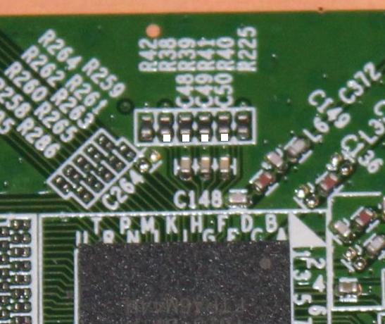
Is this a problem with pinout on router? I did not use TRST line at all. Based on MT7620 datasheet the pinout should be:
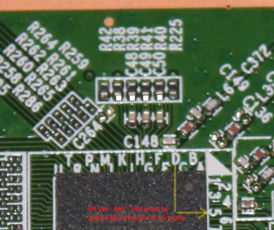
When I was playing with MT7628, which is a very similar chip design as MT7620, I've had to set a bootstrap pin or else the JTAG pins won't be defined as JTAG.
It's vocore2 JTAG bootstrap on MT7628 needs to connect a weak ground on uart pin TXD1. But I don't know if the pins are same for MT7620. I would try to ask for documentation from Mediatek (I don't see any bootstrapping info in my datasheet, only references on it).
ok. that is quite different than MT7620A. is T/R switch signal used in all configurations? if yes it might be on 2.4GHz FEMs, if not this might be hopeless attempt...
Also pull-up CS-pin(must be forced to HIGH, for example use switch between CS->3.3V) for SPI flash(if you have bootloader on NOR SPI) or pull-up CS-pin(NOT the same as for SPI! If your NAND flash have operating voltage 1.8V then must be forced CS-pin>1.8V) for NAND(if you have bootloader on this type of flash) - to prevent disabling JTAG while boot-up process.
But this should be for a while until the processor goes into JTAG mode(or halt), then the CS-pin should be released.
ok, thanks. will try this way, hopefully NAND isn't tossed since i applied 3.3 on it's CS yesterday... there is no NOR SPI otherwise i'd recover it with ch341a
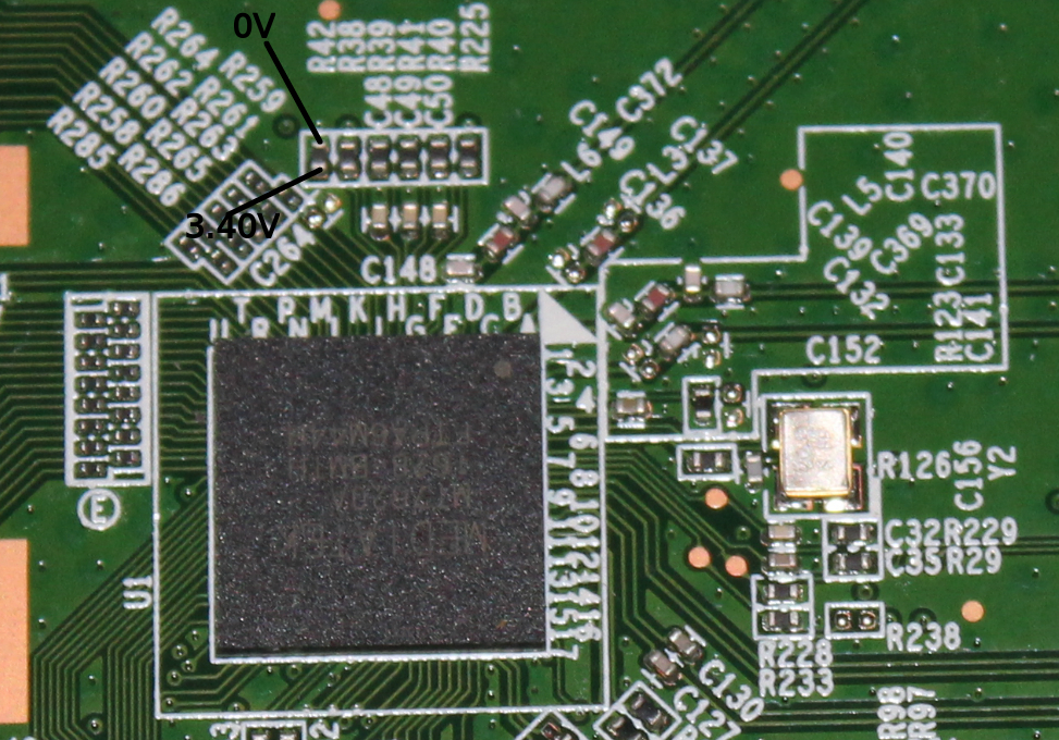
update: the pin you marked seems to connect to crystal. i don't think it's ANT_TRN
I have traced two lines on the bottom side of PCB, they both connect to CRX and LEN pins of both SKY85300-21 modules. Now I'm looking for 3.3V 8mA pin on board to short it to LEN pin line and I think that should do it.
I've put 1K resistor between 3.3V on UART header and LEN pin on FEM, CE pin on NAND is always at 3.10V (suspicious?) RE pin on NAND 3.30V, still nothing detected...
If the TRST_n pin is connected to GND it will be active and JTAG interface will be stuck in reset mode. It needs to be connected to vcc.
Also if the JTAG pins are in their normal function used for LEDs it may damage the data levels on high speeds, try to set the JTAG programmer to as low as possible speed (I have a logic buffer for amplifying the signal in my JTAG programmer).
Uboot should print something on the console, unless it is damaged too.
What would you suggest to do? Remove that resistor?
this was the last thing I did before it wouldn't respond anymore:
MT7620 # nand erase 0x00180000 0x07E80000
ranand_erase: attempt to erase a bad block at 0x02980000
ranand_erase: attempt to erase a bad block at 0x02b80000
erase failed
MT7620 # reset
That's really a speculation, but a working JTAG mode will have this pin in TRST_n mode so in input. As the input the pin will have a high impendace and will have the same potencial as GND (through that resistor). Therefore at the time of the measurement the JTAG was not enabled (either by bootstrapping or in the software setting). When the bootstrapping mode will switch the pin to input/TRST_n you will need it to drive to hard "1" (probably connect to vcc or if the JTAG interface requires TRST, to the programmer).
Just measured again: at power on it jumps to HI immediately then goes to LOW for a second or two and afterwards to HI and remains that way. Other end of the resistor is at LOW all the time. I also noticed that pin on amplifier that was pulled HI via 1K is not at 3.3V but at 2.8V. Does that sound like an issue?
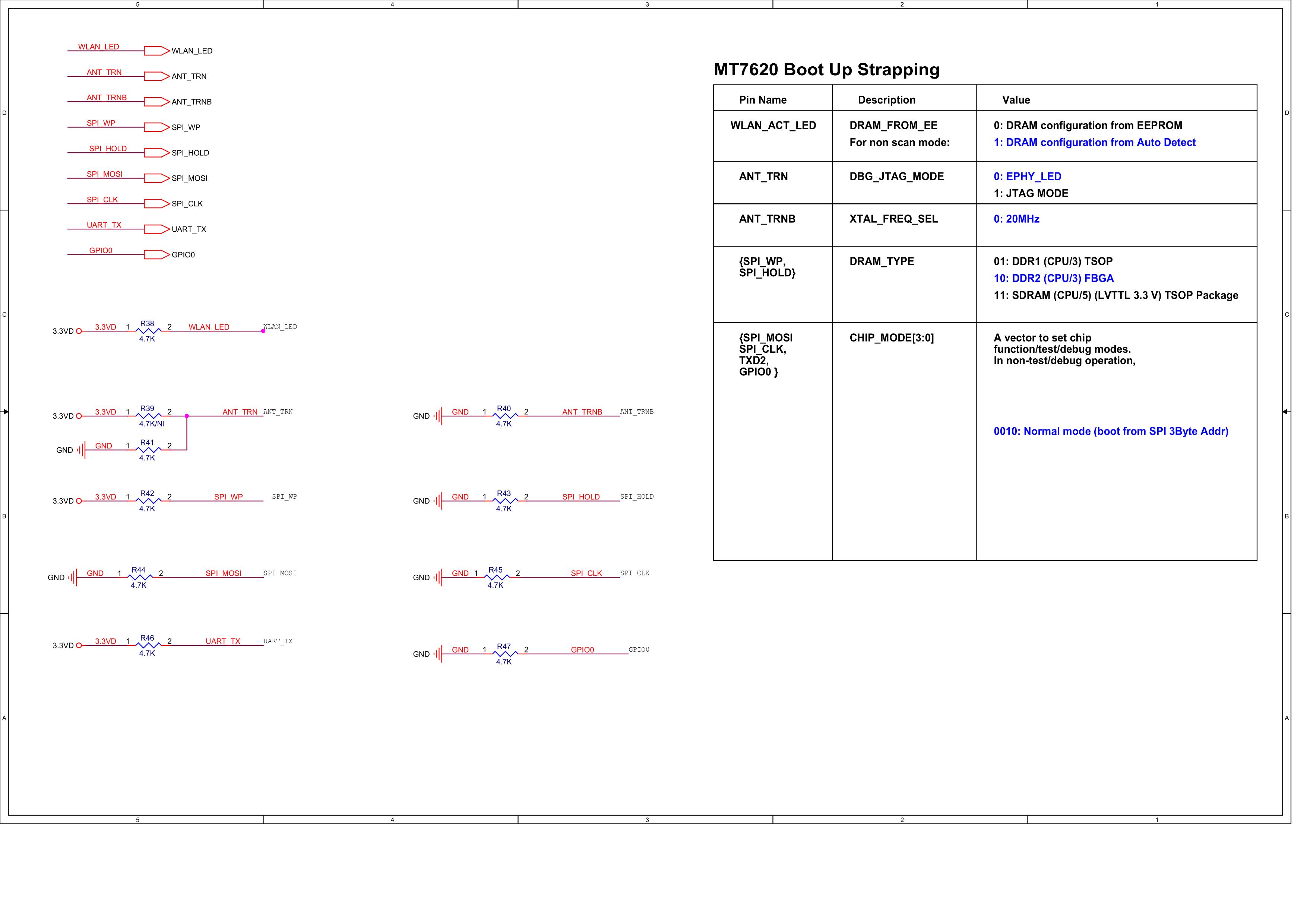
The easiest way would be probably to lower the serial resistor from the programmer. But until you enable the JTAG interface (ANT_TRN pin to "1", disable any firmware remains, which can disable JTAG in SW) it is unusable anyway.
ok, one more thing before i mess this up completely: JTAG connections are soldered in good place, or should've been soldered on the other side of R38-R41 resistors?
What value these resistors have? Are they connected to leds (most likely), to ground/vcc or they are prepared for JTAG? You need to know the circuit.
I usually connect the programmer directly to the chip (after drawing partial schematics), so before them. It should be fine to short circuit two drivers as they usually have only like 10mA (it still be overload), but the JTAG interface usually have at least 100 ohms for safety (hard 1 vs hard 0 will just safety supply to 100ohms). Your programmer should have these resistors for the exact reason. If the resistors goes into led then obviously before them and led may cause the problem for the signal. Pull resistors for vcc/gnd obviously before too and it may cause the problem with the resulting voltage divider (the programmer should supply hard "1"/"0").