This HOWTO is intended for the relatively new users who have some experience with general computing and system administration but are not (yet) comfortable with flashing firmware and need some friendly handholding to get through the process.
If you decide to go through with this procedure (which is not very difficult), I would suggest reading through this entire HOWTO before beginning the process and then referring to it as you go along.
Introduction
Check Point U-5 is a five-port router/firewall appliance. Architecture-wise, it's a fairly straightforward 32-bit PC, or, in OpenWrt terms, a generic x86. Externally, the device gives off a serious Lanner vibe (I don't know if Lanner actually made it, but it totally looks like something that came out of a Lanner factory).
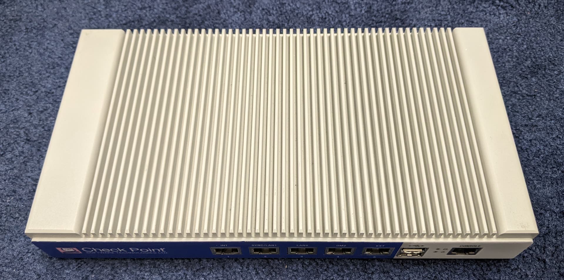
Under the hood, there is a pretty old Intel 32-bit 600 MHz processor (I've read somewhere it's a Celeron M, but didn't verify it), 1 GB of RAM, and two Ethernet cards, a single-port Fast Ethernet card (Intel 82562ET/EZ/GT/GZ) and a four-port Gigabit Ethernet card (Intel 82574L). Considering that there are plenty of places where Internet connections are slower than Fast Ethernet (100 Mbit/s), these specs are still workable for many homes or small businesses. But even if Gigabit Internet is available, there is still the option of reconfiguring one of the four Gigabit ports for Internet access (not covered in this HOWTO).
The power requirements, in case you need to source a power supply for your U-5, are 12V / 5A over a 5.5-mm barrel plug.
My unit came with a 160 GB mechanical hard drive connected via SATA, but the motherboard also has an unpopulated Compact Flash (CF) card slot. So, in theory at least, we can use either a SATA drive or a CF card as our boot media. Upon inspection of my parts inventory, I decided to go with a 16 GB SATA SSD.
There is no video output on the unit, so we will need to use the RJ-45 console port. I used an RJ-45-to-USB console cable, but there are other possibilities.
Plan your work
Here's how I thought this should go (spoiler: the plan by and large worked as intended):
- Download OpenWrt for generic x86.
- Install OpenWRT on a SATA SSD.
- Replace the unit's mechanical SATA drive with the SSD.
- Boot the unit off the SSD.
- Make necessary changes to OpenWrt default configuration.
I used a Windows computer to download OpenWrt and make the bootable SSD and a Linux computer for the rest of the operation, but I believe that one computer, either Windows or Linux, is sufficient to accomplish this (I will make notes to that end as we move along).
Download OpenWrt
Head to OpenWrt downloads site:
https://downloads.openwrt.org/
Find the Stable Release section and click on the version number (as of this writing, 22.03.0). Scroll toward the bottom of the page and click on x86. Then, click on generic. From there, download your installation image. I downloaded generic-squashfs-combined.img.gz, but it’s possible that generic-ext4-combined.img.gz might have been a better idea (the ext4 image has the primary partition that can be extended to take advantage of the entire drive; squashfs, I believe, has a non-extendable primary partition).
Install OpenWRT on a SATA SSD
When the download is complete, use your favorite image writing software to create a bootable SSD. I used Rufus on a Windows machine, but it is by no means the only game in town. Etcher is available for both Windows and Linux; Linux users, additionally, have command-line tools such as dd. I am sure I left out many other options.
To connect the SSD to the computer, I used a USB-to-SATA cable, but a direct SATA connection can be used if available.
Install the SSD into the unit
This may be a little awkward at times, but overall, it's fairly easy.
Begin by disconnecting the unit from the power supply and removing 13 (not kidding, thirteen, count them!) Philips head screws on the perimeter of the unit's bottom (see photo below). Don't bother with four screws holding the rubber feet in place, as well as with four screws sitting in a rectangular pattern in the little recesses on one side of the unit (those are hard drive mounting screws, we'll deal with them later).

Speaking of hard drive mounting screws, right now, you have your U-5 upside down. The motherboard is attached to the top (the "real" top) of the unit, where the cooling ribs are, so from where you are, it will remain in place when you lift the bottom. The hard drive is attached to the bottom of the unit, which you are about to detach. So after you remove the 13 screws, lift the bottom CAREFULLY to avoid pulling on the SATA cables connecting the hard drive to the motherboard. Filp the bottom upside down and disconnect the SATA cables from the drive (there are two, one for data, one for power). After that, you can put the bottom with the hard drive still attached to the side for a bit. We'll return to it in the cleanup phase.
Boot the unit off the SSD
With the unit still upside down and bottom taken off, connect the bootable SSD to the motherboard with the two cables. Both connectors are slightly asymmetrical, so there is only one way to connect them.
For setup and initial testing, I kept the unit in the upside-down position, with the SSD laying free inside the case.
Now connect the unit to the administrator's computer. As mentioned before, I used an RJ-45-to-USB console cable and a Linux machine. On Linux, I use a command-line utility called screen, but just as with Rufus, this is far from the only game in town. Putty is available for both Linux and Windows; there are other programs, too.
Right now, we have a bit of technical incongruency going on. The hardware, including the BIOS chip, expects to communicate at a speed of 9600 bits per second (bps). OpenWrt, on the other hand, wants to communicate at four times the speed, 38400 bps. There are two ways of dealing with this problem, we could either bring the whole thing to the lowest common denominator (9600 bps) or be aware of the issue and work around it (meaning, connect at 9600 bps if we want to mess around with BIOS or at 38400 bps if we intend to work with OpenWrt). I chose the latter. If you decide to go with the former, edit the /boot/grub/grub.cfg file to set OpenWrt's console communication speed to 9600 (note that I didn't test that, so there may be issues I am not aware of).
Note that it is generally a good idea to start the console connection first and turn the unit on second.
If you need to get into the BIOS, run:
sudo screen /dev/ttyUSB0 9600
When the screen session starts, the terminal goes blank. When that happens, turn on the U-5 and keep pressing the Tab key on the keyboard until you get a BIOS screen. If you get past meaningful output and start seeing garbage, it means you're too late; OpenWrt is already spewing out its boot messages at 38400 bps. Keep the screen session going, but turn off the U-5, turn it back on, and try starting to hit the Tab key a little earlier.
If you need to work with OpenWrt, it will be somewhat of the opposite. You start a faster connection:
sudo screen /dev/ttyUSB0 38400
then watch a little bit of garbage flying by (that would be hardware information output at 9600 bps) until OpenWrt begins to output its boot sequence.
If you use Putty, instruct it to use the following connection settings:
Speed: 9600 (or 38400 as the case may be)
Data bits: 8
Stop bits: 1
Parity: None
Flow control: None
One way or another, we should have OpenWrt booting now. When you see the message asking you to press Enter to activate the console, do so. You will be shown the OpenWrt logo and taken to the command prompt.
Make changes
When installing OpenWrt on PC-type hardware, there is always a bit of uncertainty about what hardware OpenWrt will or will not detect at first boot. This is normal and can be overcome with some patience.
In my case, OpenWrt successfully detected the single-port Ethernet card, but did not detect the four-port one. With only one port available, OpenWrt designated that port (named eth0) as the LAN interface. No problem, we can fix this.
We will start by editing the network configuration file:
vi /etc/config/network
If you're familiar with vi, you can skip this paragraph. If not, vi takes a bit of getting used to. When you first start it, vi works read-only. To switch to the editing (or insert) mode, press i on the keyboard (i for insert). When you're done editing, press Esc; this will return you to the read-only mode. To exit, you need to be in the read-only mode. Press :x to save and exit or :q to exit without saving. This is the minimum vi skillset you will need.
When you first open the network configuration file, there will be at least three sections. The first two will look like this:
config interface 'loopback'
	[a bunch of indented lines]

config globals 'globals'
	[another bunch of indented lines]
These are all good; leave them be. Edit the remainder of the file (it will probably start with config interface or config device) to look like this:
config interface 'wan'
	option ifname 'eth0'
	option proto 'dhcp'
This instructs OpenWrt to designate the only port it has detected, eth0, as a WAN port and look for a DHCP connection to an upstream device. We will use this connection to go on the Internet and find some software we're currently missing. This works in my situation, because I have an upstream router with DHCP service waiting. If your upstream router expects a device with a fixed IP address, read up on option proto 'static' and option ipaddr. You should be able to make it work that way, too.
When you're done editing, exit vi with saving (Esc, then, :x). You might want to verify that your settings have changed. Just output the settings file on screen:
cat /etc/config/network
Next, restart the networking to switch to the new configuration you just created:
/etc/init.d/network reload
Now connect the only working port you have to the upstream router. That port is labeled EXT (probably for "external") on the device's case. In the device's normal position, it would be the rightmost port, but since you have the device upside down, it's going to be leftmost. Either way. it's going to be the port located next to the two USB ports.
Give the U-5 a few moments to negotiate a connection, then test the connection. For example, run:
ping -c 3 google.com
If your connection works, you can proceed to fixing the rest of your U-5. I broke it into two parts, The Investigation and The Fix. If you don't care about how the fix was arrived at, skip The Investigation and go straight to The Fix. I would suggest, however, that you do the investigation on an off chance that your device is slightly different from mine (manufacturers occasionally produce different hardware revisions of the same model) and the fix you will need is also different from mine.
The Investigation
The reason the four-port Ethernet card isn't working right now is that there is no kernel module for it (a kernel module is a piece of software that has to be present on the device at boot in order for a device's component to work). Kernel modules can be downloaded and installed, but which damn kernel module are we missing?
To identify hardware present on the system, we will need a utility called lspci. The problem is, right now, we don't have it. But we can get it; all we need to do is install a package called pciutils.
First, ask OpenWrt to see what packages are available:
opkg update
It will take a few seconds for OpenWrt to download an inventory of what's available. Next, install the needed package:
opkg install pciutils
A few more seconds, and we have a working set of PCI utilities. Now run:
lspci -nn
If there's too much stuff onscreen, limit the output to lines containing the word "Ethernet":
lspci -nn | grep Ethernet
One way or another, you will see something like this:
01:00.0 Ethernet controller [0200]: Intel Corporation 82574L Gigabit Network Connection [8086:10d3]
02:00.0 Ethernet controller [0200]: Intel Corporation 82574L Gigabit Network Connection [8086:10d3]
03:00.0 Ethernet controller [0200]: Intel Corporation 82574L Gigabit Network Connection [8086:10d3]
04:00.0 Ethernet controller [0200]: Intel Corporation 82574L Gigabit Network Connection [8086:10d3]
05:08.0 Ethernet controller [0200]: Intel Corporation 82562ET/EZ/GT/GZ - PRO/100 VE Ethernet Controller [8086:1065] (rev 04)
Note the first four lines are nearly identical and refer to a device whose PCI identifier is [8086:10d3]. The fifth line is singular, so we can conclude that the four lines refer to the four-port Ethernet card that we need to get working, while the fifth line describes the single-port card that is working already.
Let's take a quick trip to Hardware for Linux:
https://linux-hardware.org/index.php?id=pci:8086-10d3
Note the ending of the URL; it's our PCI identifier with colon replaced by a dash. We are in luck: this is a piece of hardware known in the Linux world. The kernel module for it has been seen in Llinux sources at
drivers/net/ethernet/intel/e1000e/netdev.c
So we should be looking for something named kmod-netdev or perhaps kmod-e1000e. Googling OpenWrt kmod-netdev produces some links, but it doesn't look like they have anything to do with networking. Googling OpenWrt kmod-e1000e, on the other hand, leads to a direct hit; the package kmod-e1000e does exist and is described as Kernel modules for Intel(R) PRO/1000 PCIe Ethernet adapters.
The Fix
Now that we know which kernel module we are missing, we can install it. If you skipped The Investigation, begin by requesting an inventory of available packages:
opkg update
If you already did this, go straight to the installation:
opkg install kmod-e1000e
Once the package installs, you will see a series of messages related to the previously unknown, but now available, ports eth1, eth2, eth3, and eth4. I will show you how to bridge all those ports into a single LAN, but if you'd rather do something else, you're welcome to it; you have a fully operational and fully configurable device now. Read the documentation and configure your device to your heart's content.
You may have guessed that we're going to have another encounter with vi and /etc/config/network. If so, you've guessed correctly. Open the configuration file:
vi /etc/config/network
and add the following to its tail end:
config device
	option name 'br-lan'
	option type 'bridge'
	list ports 'eth1'
	list ports 'eth2'
	list ports 'eth3'
	list ports 'eth4'

config interface 'lan'
	option device 'br-lan'
	option proto 'static'
	option ipaddr '192.168.5.1'
	option netmask '255.255.255.0'
	option ip6assign '60'
	option igmp_snooping '1'
It's almost self-explanatory. The first part defines a bridge named br-lan, which includes four ports, eth1 through eth4. The second part tells OpenWrt to use this entire bridge as a LAN interface with a DHCP server residing at 192.168.5.1 (or whatever else you will put there to fit with your situation). DHCP settings are defined in /etc/config/dhcp; whatever is there right now should work, so we're not going to mess with it.
Save and exit (Esc, then :x), then reload the network settings same way you did before:
/etc/init.d/network reload
Test your router by connecting a client device to it and accessing the Internet and the router itself, both via SSH (in my example that would be ssh root@192.168.5.1) and through LuCI (https://192.168.5.1). Set the root password, if you haven't already (passwd on the command line or System >> Administration in LuCI). Close the screen session (press Ctrl-a, then k, then y). Disconnect the console cable and put it away util the next time you need it.
Putting the U-5 back together
If everything worked, congratulations! You have a working router. The only problem is, it doesn't have a bottom and its SSD is not attached to anything. So let's fix it.
Turn off your router and temporarily disconnect the SSD from its cables.
Next, pick up the bottom that you have put aside earlier. Note the way the hard drive is oriented (meaning, which way its SATA connectors face). Mark it on the inner side of the bottom or take a photo; this will help you to install the SSD correctly.
Undo the four screws holding the hard drive in place. Note that those screws connect to four standoffs with rubber buffers. Those standoffs, in turn, connect to threaded holes in the case of the hard drive. So unscrew the standoffs from the hard drive and screw them into your SSD. Then install the SSD, now on standoffs, onto the bottom. Be sure to orient the SSD the same way the hard drive was oriented. Connect the SATA cables to the SSD and put the bottom back in place.
It is possible that you will have a bit of trouble putting the damnable 13 screws back in place. If you do, do not force the screws in place. Instead, loosen the six screws holding in place the back panel of the device. This will allow some play, so the bottom will settle down nicely. After you reinstall the bottom, retighten the screws holding the back panel and enjoy your new router.