DGS-1210-10MP as a spin-off from DGS-1210-10P

Do anyone have the D-Link original memory partitions/mapping for DGS-1210-10P?

I have looked at the memory partitions in boot log for the dgs-1210-10mp and compared with the dgs-1210-10p dts file and I highly doubt that the d-link memory mapping was originally named and partitioned as it is called in the openwrt dts file.

What openwrt call “uboot” partition, d-link call “boot”.

But the biggest difference seems to be that openwrt dts file has bunched together the two partitions positioned between the env2 and kernel2 and called that area “firmware”. And the rest of the memory partitions after “firmware” are identical between openwrt and d-link?

And they both have the same 32MB memory chip.

You could help by posting what you have on the dgs-1210-10mp

1 Like

Here you go:

Probe: SPI CS1 Flash Type MX25L25635F
Creating 9 MTD partitions on "Total SPI FLASH":
0x00000000-0x00080000 : "BOOT"
0x00080000-0x000c0000 : "BDINFO"
0x000c0000-0x00100000 : "BDINFO2"
0x00100000-0x00280000 : "KERNEL1"
0x00280000-0x00e80000 : "ROOTFS1"
0x00e80000-0x01000000 : "KERNEL2"
0x01000000-0x01040000 : "SYSINFO"
0x01040000-0x01c40000 : "ROOTFS2"
0x01c40000-0x02000000 : "JFFS2"

And that's how it looks once OpenWrt is installed:

[    1.545076] Initializing rtl838x_nor_driver
[    1.549924] SPI resource base is b8001200
[    1.554495] Address mode is 4 bytes
[    1.558460] rtl838x_nor_init called
[    1.565806] rtl838x-nor b8001200.spi: mx25l25635e (32768 Kbytes)
[    1.572760] 8 fixed-partitions partitions found on MTD device rtl838x_nor
[    1.580438] Creating 8 MTD partitions on "rtl838x_nor":
[    1.586377] 0x000000000000-0x000000080000 : "u-boot"
[    1.594480] 0x000000080000-0x0000000c0000 : "u-boot-env"
[    1.602978] 0x0000000c0000-0x000000100000 : "u-boot-env2"
[    1.611494] 0x000000100000-0x000000e80000 : "firmware"
[    1.637241] 0x000000e80000-0x000001000000 : "kernel2"
[    1.645547] 0x000001000000-0x000001040000 : "sysinfo"
[    1.653813] 0x000001040000-0x000001c40000 : "rootfs2"
[    1.662078] 0x000001c40000-0x000002000000 : "jffs2"

Good luck!

1 Like

Thanks, I have no secrets on this project but I was so curious so I started the post from the smartphone before I was at home.

Device data from system page of original firmware:


Device Information

Device Type DGS-1210-10MP Gigabit Ethernet Switch

System Name DGS-1210-10MP

Boot Version 1.01.001

System Location

Firmware Version 6.20.007

System Time 01/01/2020 00:26:02

Hardware Version F1

System Up Time 0 days , 0 hours , 26 mins , 31 seconds

Serial Number "sanitized"

Login Timeout (minutes) 30

MAC Address "sanitized"

Original DGS-1210-10MP boot log:


U-Boot 2011.12.(2.1.5.67086)-Candidate1 (Jun 22 2020 - 15:03:58)

Board: RTL838x CPU:500MHz LXB:200MHz MEM:300MHz

DRAM: 128 MB

SPI-F: 1x32 MB

Loading 1024B env. variables from offset 0x80000

Board Model = DGS-1210-10MP-F1 Cameo_bdinfo_get_BoardID [293]

Switch Model: RTL8380M_INTPHY_2FIB_1G_DEMO (Port Count: 10)

Switch Chip: RTL8380

**************************************************

#### RTL8218B config - MAC ID = 8 ####

Now Internal PHY

Net: Net Initialization Skipped

rtl8380#0

Hit Esc key to stop autoboot: 0

Loading Runtime Image ......

## Booting kernel from Legacy Image at b4100000 ...

Image Name:

Created: 2020-06-22 15:09:40 UTC

Image Type: MIPS Linux Kernel Image (gzip compressed)

Data Size: 1035510 Bytes = 1011.2 KB

Load Address: 80000000

Entry Point: 80262000

Verifying Checksum ... OK

Uncompressing Kernel Image ... OK

Starting kernel ...

Linux version 2.6.19 (simon@208Server) (gcc version 3.4.4 mipssde-6.03.00-20051020) #20 PREEMPT Mon Jun 22 15:09:26 CST 2020

CPU revision is: 00019070

Determined physical RAM map:

memory: 02000000 @ 00000000 (usable)

User-defined physical RAM map:

memory: 07a00000 @ 00000000 (usable)

Built 1 zonelists. Total pages: 30988

Kernel command line: console=ttyS0,115200 mem=122M noinitrd root=/dev/mtdblock4 rw rootfstype=squashfs csb=0x0142F49D cso=0x0866F1AF csf=0x56B69CCF sfin=<NULL>,32MB,10887200;10887200

Primary instruction cache 16kB, physically tagged, 4-way, linesize 16 bytes.

Primary data cache 16kB, 2-way, linesize 16 bytes.

Synthesized TLB refill handler (20 instructions).

Synthesized TLB load handler fastpath (32 instructions).

Synthesized TLB store handler fastpath (32 instructions).

Synthesized TLB modify handler fastpath (31 instructions).

PID hash table entries: 512 (order: 9, 2048 bytes)

Dentry cache hash table entries: 16384 (order: 4, 65536 bytes)

Inode-cache hash table entries: 8192 (order: 3, 32768 bytes)

Memory: 121088k/124928k available (2015k kernel code, 3724k reserved, 421k data, 108k init, 0k highmem)

Mount-cache hash table entries: 512

Checking for 'wait' instruction... available.

NET: Registered protocol family 16

NET: Registered protocol family 2

IP route cache hash table entries: 1024 (order: 0, 4096 bytes)

TCP established hash table entries: 4096 (order: 2, 16384 bytes)

TCP bind hash table entries: 2048 (order: 1, 8192 bytes)

TCP: Hash tables configured (established 4096 bind 2048)

TCP reno registered

squashfs: version 3.3 (2007/10/31) Phillip Lougher

JFFS2 version 2.2. (NAND) (C) 2001-2006 Red Hat, Inc.

io scheduler noop registered

io scheduler anticipatory registered

io scheduler deadline registered

io scheduler cfq registered (default)

Serial: 8250/16550 driver $Revision: 1.1.1.1 $ 1 ports, IRQ sharing disabled

serial8250: ttyS0 at MMIO 0x0 (irq = 31) is a 16550A

Probe: SPI CS1 Flash Type MX25L25635F

Creating 9 MTD partitions on "Total SPI FLASH":

0x00000000-0x00080000 : "BOOT"

0x00080000-0x000c0000 : "BDINFO"

0x000c0000-0x00100000 : "BDINFO2"

0x00100000-0x00280000 : "KERNEL1"

0x00280000-0x00e80000 : "ROOTFS1"

0x00e80000-0x01000000 : "KERNEL2"

0x01000000-0x01040000 : "SYSINFO"

0x01040000-0x01c40000 : "ROOTFS2"

0x01c40000-0x02000000 : "JFFS2"

IPv4 over IPv4 tunneling driver

TCP cubic registered

NET: Registered protocol family 1

NET: Registered protocol family 10

lo: Disabled Privacy Extensions

NET: Registered protocol family 17

VFS: Mounted root (squashfs filesystem) readonly.

Freeing unused kernel memory: 108k freed

init started: BusyBox v1.00 (2020.06.22-07:08+0000) multi-call binary

Starting pid 14, console : '/etc/rc'

Init RTCORE Driver Module....OK

tun: Universal TUN/TAP device driver, 1.6

tun: (C) 1999-2004 Max Krasnyansky <maxk@qualcomm.com>

passwd file exit

ssdh_config file exit

Complete NpHwInit

RTK.0> open /bin/poe.bin fail

POE_SUCCESS

device TAP0 entered promiscuous mode

DGS-1210-10MP login:

DGS-1210-10MP original memory partitions (from boot log):


Probe: SPI CS1 Flash Type MX25L25635F

Creating 9 MTD partitions on "Total SPI FLASH":

0x00000000-0x00080000 : "BOOT"

0x00080000-0x000c0000 : "BDINFO"

0x000c0000-0x00100000 : "BDINFO2"

0x00100000-0x00280000 : "KERNEL1"

0x00280000-0x00e80000 : "ROOTFS1"

0x00e80000-0x01000000 : "KERNEL2"

0x01000000-0x01040000 : "SYSINFO"

0x01040000-0x01c40000 : "ROOTFS2"

0x01c40000-0x02000000 : "JFFS2"

@sumo It seems that my DGS-1210-10MP has the same original memory setup as the -10P, also that the "KERNEL1" and "ROOTFS1" it put together under "FIRMWARE" in the OpenWRT memory mapping.

Do I need any special file ("memory mapping file") to make a -10MP version of these two files from the -10P commit to make this OpenWRT memory setup working?
https://git.openwrt.org/?p=openwrt/openwrt.git;a=commit;h=c78e123d5a5e7c3baa74f326613a14f7e99a29a3

target/linux/rtl838x/dts/rtl8382_d-link_dgs-1210-10p.dts

target/linux/rtl838x/image/Makefile

The other files in the commit seems to apply to all devices in the family?

Another question?

I have tried to find a official installation method for -10P but the only family device with a mentioned install method is the -16 device

OpenWrt installation using the TFTP method and serial console access
Is that the method that I should be using on the -10P(MP) also?


tftpboot 0x8f000000 <ipofyournetworkport>:<openwrtimagename>

Is the memory address 0x8f000000 the right one? I have a small memory that somewhere in the big RTL838x post that it was another address mentioned?

Sooner or later we have the POE question but I think we start by getting basic OpenWRT installed to begin with.
I would assume those devices are equal besides the PoE side of things but I am no expert on those Realtek targets.

At least this is also how I installed OpenWrt on mine.

Let me check my notes as I always keep logs of everything I do...

Yep, makes sense.

1 Like

No, for me 0x8f000000 actually worked.

U-Boot 2011.12.(2.1.5.67086)-Candidate1 (Oct 20 2017 - 15:42:41)

Board: RTL838x CPU:500MHz LXB:200MHz MEM:300MHz
DRAM:  128 MB
SPI-F: 1x32 MB
Loading 1024B env. variables from offset 0x80000
Board Model = DGS-1210-10P-F1 Cameo_bdinfo_get_BoardID [293] 

Switch Model: RTL8380M_INTPHY_2FIB_1G_DEMO (Port Count: 10)
Switch Chip: RTL8380
**************************************************
#### RTL8218B config - MAC ID = 8 ####
Now Internal PHY
Net:   Net Initialization Skipped
rtl8380#0
Hit Esc key to stop autoboot:  1  0 
u-boot># 
DDP Timeout.

Abort
Ctrl-c was pressed..(Changing to u-boot console mode(0)) 

<INTERRUPT>
u-boot># rtk network on
Enable network
Force port28 link up 1G
Please wait for PHY init-time ...

u-boot># setenv ipaddr 192.168.10.2
u-boot># setenv serverip 192.168.10.1
u-boot># tftpboot 0x8f000000 test/flash.bin
Using rtl8380#0 device
TFTP from server 192.168.10.1; our IP address is 192.168.10.2
Filename 'test/flash.bin'.
Load address: 0x8f000000
Loading: *Got ARP REPLY, mac addr (54:05:db:75:f7:79), ip addr (192.168.10.1)
#################################################################
	 #################################################################
	 #################################################################
	 #################################################################
	 #################################################################
	 #################################################################
	 ###################
done
Bytes transferred = 5992809 (5b7169 hex)
u-boot># bootm

Loading Runtime Image ......
## Booting kernel from Legacy Image at 8f000000 ...
   Image Name:   MIPS OpenWrt Linux-5.4.124
   Created:      2021-06-13  22:02:19 UTC
   Image Type:   MIPS Linux Kernel Image (gzip compressed)
   Data Size:    5992745 Bytes = 5.7 MB
   Load Address: 80000000
   Entry Point:  80000400
   Verifying Checksum ... OK
   Uncompressing Kernel Image ... OK

Starting kernel ...

[    0.000000] Linux version 5.4.124 (builder@buildhost) (gcc version 8.4.0 (OpenWrt GCC 8.4.0 r16172-2aba3e9784)) #0 Sun Jun 13 22:02:19 2021
[    0.000000] RTL838X model is 83806800
[    0.000000] SoC Type: RTL8380
[    0.000000] Kernel command line: 
...
1 Like

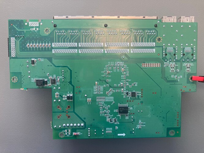
DGS-1210-10MP F1, main circuit board underside:

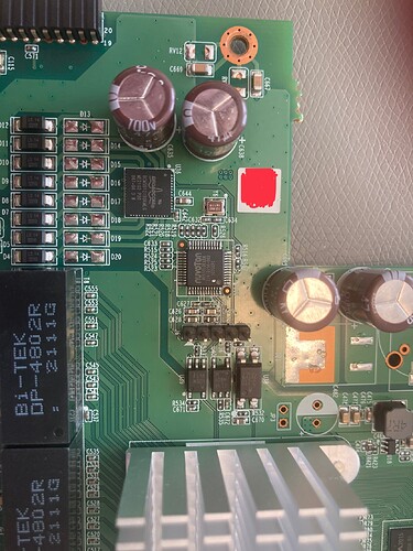
DGS-1210-10MP F1, main circuit board PoE controller:

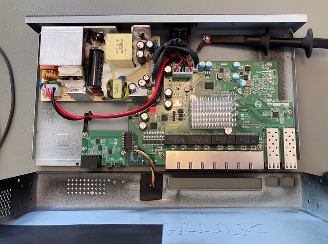
DGS-1210-10MP F1, overview chassi with mounted serial connector:

If anyone tries to open the lid, you do not lift it up! You pull the lid backwards after releasing the screws on the side and bottom because there is a rail in the front that hooks under the front panel.

And there seems to be three different isolated ground potentials on the device! Power ground on the PSU/chassi. CPU ground and PoE ground.

When I found out that I realized that I had to put a plastic socket on the chassi for my metallic stereo 3,5mm serial connector. The serial ground is CPU ground but the chassi is power grid ground.

Unfortunately the heatsink is soldered to the circuitboard vias.

Luckily, I just exited my 3 Dupont wires via Kensington lock opening without having to touch anything chassis.

Wait a minute, cooler? Ah, you mean the heatsink, yep.

Sorry, fixed that😄

I wanted the connector in the front panel because it is so hard to get access from behind when it is mounted in the 19” rack.

But I don’t know what the potential of the chassi is on the -10P model since the PSU is external and only 54VDC enters the chassi?

Luckily, my rack is easily accessible from both front and back.

Yep, that's true. Almost forgot about mine having this inconvenient external power brick.

Nice. Thanks for the photos. Fascinating to see the all those paths across the whole board just to put the console, buttons and LEDs on the opposite side of the board relative to the SoC and RTL8231. Makes you wonder if they do board layout or case design first :slight_smile:

I believe the PoE controller isolation and separate grounds, with chassis being connected to outside/power ground, is pretty common for PoE switches. Definitely something to be aware of if adding connectors to the chassis. Or when snooping on the PoE micro controller.

1 Like

I don't have this switch, but there is usually a separate external ground connection on switches with external PSUs. At least there is on the ZyXEL GS1900-10HP. Whether you connect that or not is up to you...

2 Likes

Also the -10MP has the potential connector on the back.

I usually have those connected to a earth distribution block.

1 Like

D-link at least have straight screw holes on the same places as the other hole compared to Ubiquinti.

I have during the last month learned how to compile the firmware from source.

But that is a one way street, I download and build. How do you set up a development build system if you want as a base the master code for example. But also need to make own files like the dts and changes to the make file (that seems to be updated in source during the last tree days). And in the future also ad on the poe package.

And also be able to do git pull to update the actual source code and at the same time not loose al the setup for the -10mp?

Assuming you started with https://openwrt.org/docs/guide-developer/toolchain/install-buildsystem then those questions are mostly about git workflows. If you haven't used git before, then try looking at some of the many tutorials on the net. Experiment a bit with different branches, merging and rebasing.

It can take some time to get used to, but is well worth it. You'll find that it's easy to do what you want by maintaining one or more local branches with your development code.

1 Like

That is pretty much how I have built my firmwares for the operational devices.

I choosed to have one unique buildroot on the computer for every device just for simplicity since they all have some different settings, configs and packages. And the switch will run with master to begin with since the chip family development is very much still alive.
It felt easier to work in different buildroot than to have all in one single buildroot and different settings and change checkout for different devices.

Do I need to do a openwrt fork on my github account to have that as a “middle bridge” for source pull and adding my modifications?
Or should it be possible to develop this directly on the computer

You can keep everything local. That's up to you to decide. And there is no problem (except disk usage) having multiple local trees if you prefer.

1 Like

Ok, so now I have installed a 22.03-snapshot on my switch as a copy with new device name from 1210-10p and the ports works. The LED’s seems to show Act.

The only hardware that doesn’t seem to be alive is the two buttons.
The Mode button that changes the LED between act and poe, note that I haven’t installed PoE yet. But is that button activated on any other device in this family?

The reset button isn’t doing anything, I have a small memory that it is something more with that on D-link devices?

PoE, it seems to be two options here?
https://patchwork.ozlabs.org/project/openwrt/patch/20210511152243.1167160-1-john@phrozen.org/

or
https://git.openwrt.org/?p=openwrt/staging/blogic.git;a=tree;f=package/rtl83xx-poe;h=59e990a702ef41a1dc2276ee9ea54cabfdb9566e;hb=2540faec92abf8f5e52eae0e77bfbdb47457252d
which one do you use?