This post summarizes related forum posting.
What does this do for you?
The WAN port is normally for an "uplink" to a cable modem or an outside network. Nodes on the WAN side cannot "see" nodes on the LAN side. Here describes the configurations needed to make the router behave as a network switch such that this invisible "barrier" is removed and there will be no "sides". The WAN port is to behave like a regular LAN port.
The steps below outline how I configured my router into a 5 port high speed network switch. OpenWrt brings about versatile use-case like mine.
Step 1: Join LAN and WAN into a VLAN
Notice the black bar in this screenshot. It is the pull down menu. Use this to navigate to "Network->Switch" page on which there used to be two lines. This screen showed after line "2" (corresponding to VLAN-2) has been deleted leaving only line "1" (VLAN-1). Notice that WAN (right-most) has been set to "untagged". With this setting, the WAN port sits on the same VLAN-1 (virtual LAN) as the regular LAN ports. They are all "untagged" on the same line. Think of it as "making my red WAN port to be the same as the other yellow LAN ports". (On my router the WAN port is red (colour code) whereas the 4 LAN ports are yellow.)

Step 2: Delete the WAN interface(s)
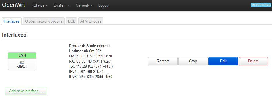
Navigate to "Network->Interfaces". The screenshot shows that I have deleted "WAN" leaving only "LAN". Do not be alarmed as this deletion has removed the "WAN interface(s)" but not the WAN physical port and not the functioning of the WAN port.
Step 3: Configure the LAN interface
There are a number of parameters to set in this step. The parameters are set in a pop up window which shows a "Save" button on the lower right.
Click "Edit" button on the right (corresponding to "LAN" on the left). If in these steps you decide to press the "save" button, the pop up window will close. We can click "Edit" to cal up the pop up window again to add changes to our parameters.
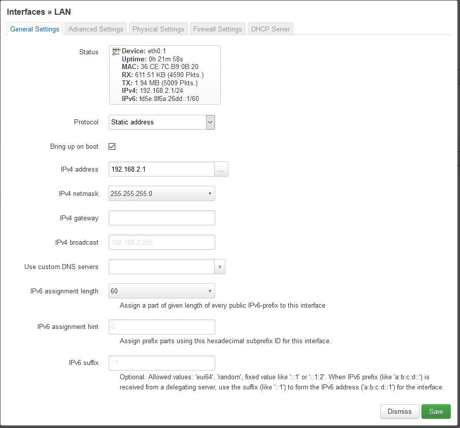
Here shows the "General" tab. If Protocol is not "Static address", the screen will not be exactly the same as this screen shot above. In that case, we need to first "switch" into the "Static address" protocol step 3a before proceeding to step 3b.
Step 3a: Switch Protocol to "Static address"
Locate the "Protocol" field, click to select from the pull-down list to change it and there will be a button showing "Switch protocol". Here is an example how the screen will look like.
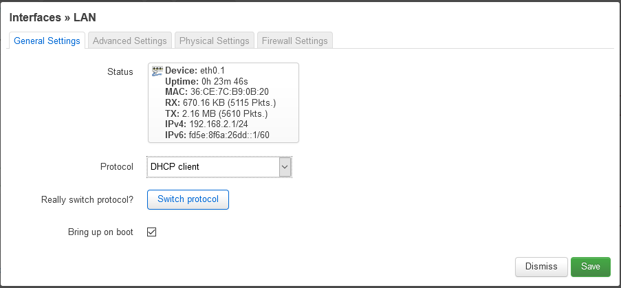
This screen shot is incorrectly showing "DHCP client". It should be "Static address" in this field. Once the protocol has switched to static address, the screen layout will be showing "IPV4 address" field as shown in the previous screen shot.
Do not forget to click the "Switch protocol" button.
Step 3b: Assign a "Static address"
In my use case, an IP address 192.168.2.1 is assigned to this field (step 3 screen shot) which is intentionally placed outside of my network IP 192.168.1.XXX. This is done so the network would not "see" the network switch that we are configuring as a node on the network.
Step 3c: Set interface to eth0.1
The settings needed to be on the "Physical Settings" tab is as shown. If we click to pull down "Interrface", we can see that eth0.1 corresponds to "Switch VLAN" which is the "VLAN-1" in step 1.

Step 3d: Extra settings - Workaround to "random" MAC address
Do not dismiss the "Interfaces-LAN" screen yet. On the "Advanced Setting" tab, the "Override MAC address" field is given a value. If we don't, the MAC address will change every time the router is booted up.
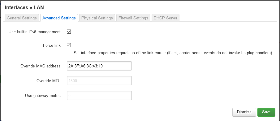
Although this step is not strictly necessary, the MAC address of the device changes "randomly" in every running session does feel odd. Please feel free to incorporate this "fix".
Step 3e: Check firewall-zone
On the "Firewall Settings" tab, check the firewall zone. Here is my example.

Note the zone name. The check to make sure firewall does not get into the way will be presented in step 4.
Step 3f: Apply the changes
Click "save". The pop up window will dismiss. Observe that "Interface has N changes" text is shown as in this example:
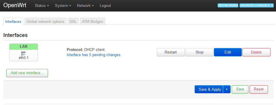
Click "Save & Apply".
Step 4: Check firewall
From pull down menu "Network->Firewall", the firewall should accept traffic since we are implementing a network switch which by nature does not filter traffic. Here is my example. The green "lan" on the left column below "Zone => Forwardings" is the firewall name that we noted in step 3e.

Step 6: Preventive work-around
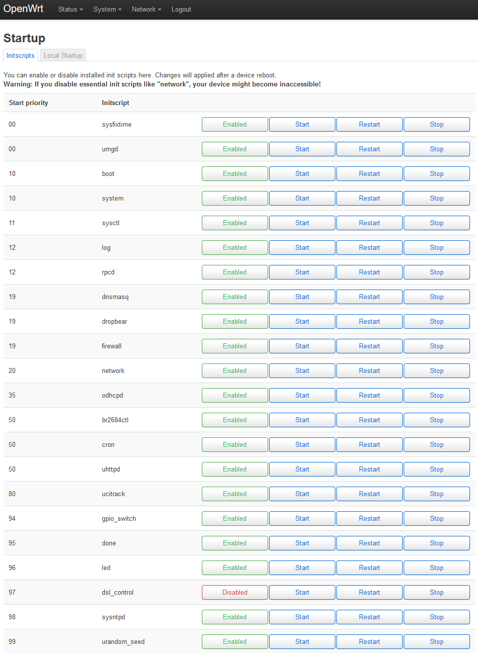
This extra step would probably be only needed for "BT Home Hub 5A". If the red WAN port is not connected or if it is void of traffic, the device will generate large amount of internal "fake" traffic. It will eventually reset. Since we are configuring our device as "network switch", we can further prevent this problem by disabling dsl_control. This entry can be accessed by "System->Startup". Here is an example:
Conclusion
The steps that I used to convert the WAN port to the fifth LAN port is outlined above.
Hardware and firmware
The above notes are based on
- Sagemcom Plusnet Hub One (Model BT Home Hub 5A)
- OpenWrt 19.07.4 r11208-ce6496d796
- LuCI openwrt-19.07 branch git-20.247.75781-0d0ab01
Further details:
- Architecture is described as xRX200 rev 1.2
- Believed to be MIPS dual core processor
- Printed circuit borad marked "2003" E89382, 08B1-1X76100
The steps that implements work-arounds may not be needed on your hardware.