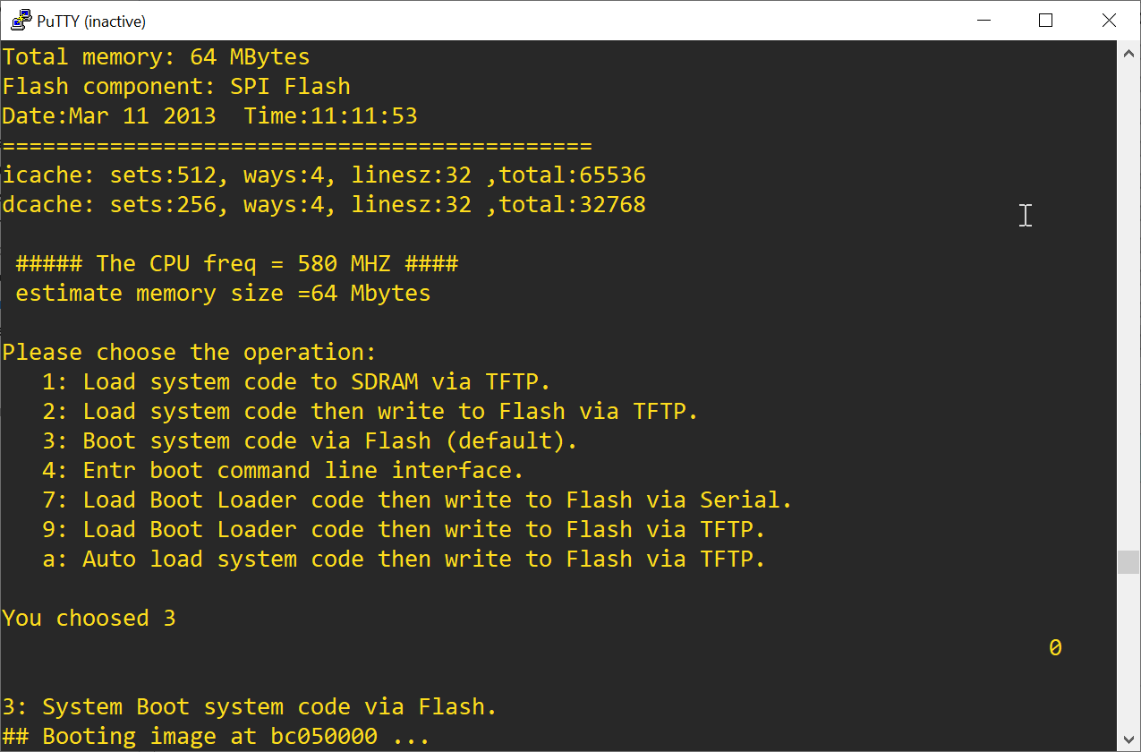
Following a detailed write-up on how to flash the Zyxel NBG6503 I'm unable to access the u-boot menu that will start the process of tftp-downloading an image etc.
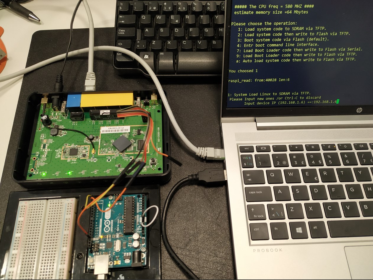
I'm using the UART of an Arduino Uno board to access the serial interface of the router. This may sound quirky but the Arduino board makes it simple to interface pin headers and there's a 3.3 VDC source available as well. I'm using a voltage divider for the serial input that will output 3.4 VDC instead of the 5.0 VDC logic levels coming from the Arduino board.
Strange thing is, the router does not appear to recognize any serial input at all. It will only activate the third and default menu option ("Boot system code via Flash"). I have set up a TFTP server on 10.10.10.3/24 but there's no attempt from the device to access it (monitoring the interface with Wireshark).
I've also tried using a USB-to-TTL-cable connected through the same voltage divider setup for serial input, but this setup gave me only gibberish serial output using the same parameters as before (57600 bps, 8N1, no flow control).
I've tried powering the device over the normal DC input and also been using the 3.3 VDC input pin in parallell. Ethernet interfaces will only turn on when powered over the 12 VDC input.
Tx cable goes on Rx connector on router and Rx cable goes to Tx connector on router.
Specify “voltage divider”, I am not so sure that is a good idea on serial interface connector pins since they are not GPIO logical input pins?
But even if you have a voltage divider on Tx you probably need a voltage increaser on Rx.
Are you sure on this speed? Pretty much all routers usually have max 115200.
Well, funny thing is when using the Arduino Uno's UART you connect RX-RX and TX-TX (see explanation by commenting user DuinoSoar in link below)
The voltage divider is needed to pull down the 5.0 VDC signal (sent from the Arduino) to 3.3 VDC logic levels. This is common practice when using logic circuits with different voltages. A voltage as high as 5.0 VDC might damage a 3.3 VDC input.
There is, however, no need to pull the 3.3 VDC level TX line up to 5.0 VDC, because it will hit the tolerance threshold and thus be interpreted correctly by the UART.
To be clear, I'm receiving readable console output from the router.
The Tx is the output signal. You cant connect output to output. The output from transmitter goes to input on receiver.
That means Tx goes to Rx and vice versa in the other direction.
The device is not recognizing my serial input when I try to activate menu option 1 (or any of the other options). I will just skip to default option 3 and continue booting. As per instructions, one should press 1 and then power up the device.
I'm just using the UART of the Arduino board. The Atmel chip can be bypassed, i.e. it is not executing any code. My input is sent from my terminal emulator (PuTTY) to the UART and then to the device. There's really nothing different than using a USB-to-TTL-converter.
So that means that your serial connection is physically working for at least the Tx (router) > Rx (serial adapter) that you are using.
If it is not accepting input, check the other line (Tx from the adapter and Rx on the router) -- make sure you have the correct pins and that your wire is making good physical contact.
As I stated before, you should only be using 3 wires (Tx, Rx, Gnd). There should be no voltage dividers on the Tx and Rx lines.
If you are able to provide input and then you get gibberish, it may mean that it has switched to a different baud rate after it begins the boot process. You might need to reconnect at 115200 8-N-1 (but this is a guess).
So the output on Tx on the router is 3,3V minus voltage drop in the cable, connectors and PCB. You simply cant get a guaranteed legal logic 1 (3,5V) on the input on the Aurdino with 3,3V on the router since UART is TTL technology.
Are you using passive or active level shifters on the other line?
I strongly recommend to use active level shifters in both directions to get it working.
Or buy a 3,3V serial adapter if there is anyone left to buy.
A second USB-to-TTL-converter cable produced gibberish serial output (tried setting serial parameters both in PuTTY and through Windows device manager). The Arduino Uno board UART setup produced fully readable serial output.
Removing the voltage divider for RX will probably damage the input, but it might be worth a last try since I'm about to toss this router anyway...
Most consumer devices like this use a 3.3V (or max 5V) TTL serial connection. If your device has a proper "console" port (on a RJ45 or DB9 connection), that is typically RS232 (12V) serial.
The USB-TTL adapters come in a variety of flavors with respect to nominal voltageand tolerances, sometimes you can set them by means of jumpers or solder bridges. 5V and 3.3V adapters will often (but not always) be functional at either 5V or 3.3V and not cause any damage in either direction if one side is higher than the other. Read the documentation for your specific adapter.
I thought my screenshot from the terminal proved that 3.3V will be interpreted correctly on 5.0V input. Regarding V_IH, I found this on forum.arduino.cc:
For an Uno, it is about <0.3Vcc for low, and >0.6Vcc for high (about 3V)
But back to my failing serial input. Maybe I'll hook up the RX line to a scope to fully determine the cause. A logic level shifter is also worth a try.
This is quite commonly done but keep resistances low so that there is little chance the rise times and fall times of the data signal are not unduly lengthened.
I don't have the device here now, but will try lowering the resistance values after the weekend.
Well, turns out the serial input worked like a charm after removing the voltage divider all together. Tried a 100/200 Ohm-divider with no luck before discarding it completely. The serial port on the device is clearly marked 3.3V so please don't blame me for being too cautious with the RX input voltage.
Anyway, if someone else want to save a few bucks on a USB-TTL-converter, this Arduino Uno board UART setup is wired as follows:
Jumper cable shorting Arduino Uno's RESET and GND
Arduino GND - Zyxel NBG6503 serial GND
Arduino RX - device RX (yes, that is correct)
Arduino TX - device TX (that is also correct)
device 3.3V not connected (device is powered over normal DC input)