I added.
I added all gpio to pinmux.
Done:
I added.
I added all gpio to pinmux.
Done:
Thanks 
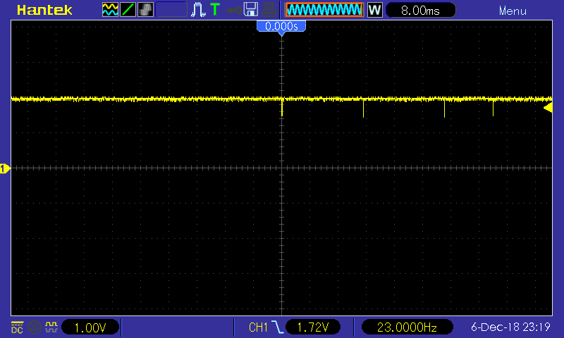
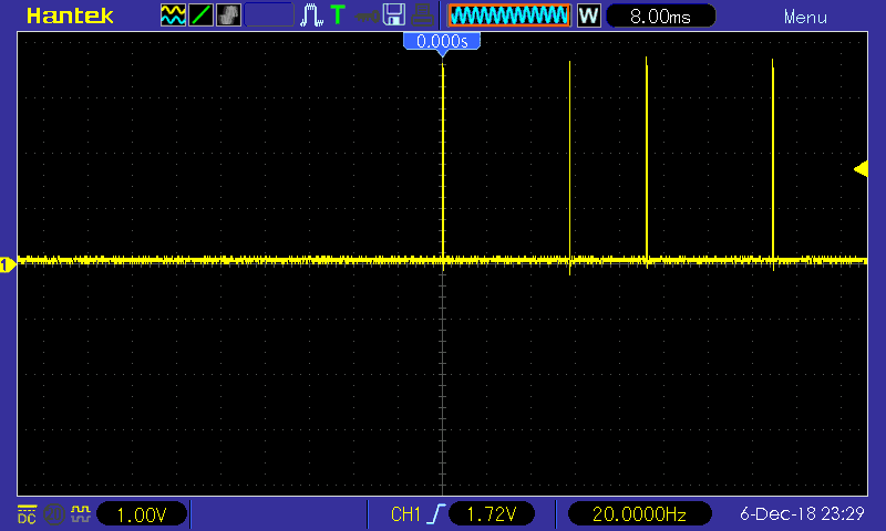
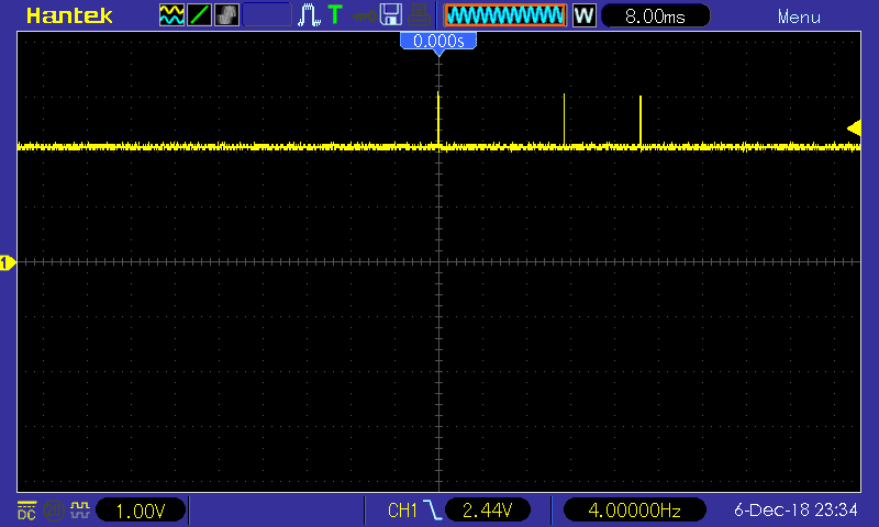
However turns out spawning a new process from within lua takes about 4 milliseconds, while using && to concatenate individual gpio commands can toggle a pin within about 150 µs...
So I was trying to do it rather complicated at first, but then it does not need any sleep in microseconds range at all, just milliseconds for the spacing between pulses...
gpio_start = 11
gpio_end = 13

for pin = gpio_start, gpio_end do
  os.execute("echo '" .. pin .. "' > /sys/class/gpio/export")
end

while true do
  for pin = gpio_start, gpio_end do

    -- set "left bit" (burst start) for trigger
    n = pin + 32

    for i = 5, 0, -1 do
      exp = 2 ^ i
      if n >= exp then
        n = n - exp
        -- write single pulse
        os.execute("echo 'out' > /sys/class/gpio/gpio" .. pin .. "/direction && " ..
                   "echo '0' > /sys/class/gpio/gpio" .. pin .. "/value && " ..
                   "echo '1' > /sys/class/gpio/gpio" .. pin .. "/value && " ..
                   "echo '0' > /sys/class/gpio/gpio" .. pin .. "/value && " ..
                   "echo 'in' > /sys/class/gpio/gpio" .. pin .. "/direction")
      end

      -- inter-pulse interval
      os.execute("usleep 2000")

    end
  end

  os.execute("usleep 100000")

  --break
end
LED on GPIO 11:
USB 0.5A enable on GPIO 13:
USB 1A enable on GPIO 12 goes to Pin 7 (CLT2) of TPS2546:
Will add this to the schematic maybe tomorrow, and do some more GPIO fuzzing (curious about CLT3  ) ...
) ...
However GPIO#0 will cause reset instantly, the shell is just too slow when concatenating pin access with &&, so we probably need a real c program to make the pulses even shorter (if possible at all) or find something else...
It is weird that I can now even
echo "12" > /sys/class/gpio/export
echo "13" > /sys/class/gpio/export
echo "out" > /sys/class/gpio/gpio12/direction
echo "out" > /sys/class/gpio/gpio13/direction
echo "0" > /sys/class/gpio/gpio12/value
echo "1" > /sys/class/gpio/gpio13/value
and both USB ports and the off switch will be working 
Is there anything different now compared to previous images? I can even export both LEDs and overwrite the current state that was set by bootloader...
Maybe something regarding the UARTF on Pins 7 - 10:
RXD   GPIO#10
CTS_N GPIO#9
TXD   GPIO#8
RTS_N GPIO#7
actually we only need GPIO#10 for receiving the battery status from MSP.
// edit: removed info about weird effects that were due to mechanical connection issues //
Also GPIO 7-10 could not be exported for testing (i.e. I still don't know where CLT 3 and EN of the USB Charger are connected), 10 is obviously for UART RX, but is there some way of configuring only GPIO#10 for hardware UART, but leave the others floating / disable special function? I suspect there might be additional control pins here.
In any case, I hope it will still be wórking when USB pins are exported by default again during boot
Maybe it could finally be the last image before PR? 
I have done with DIR-506L: https://github.com/openwrt/openwrt/pull/1590
Now Im with you, just restored mine 510L, now it use sop8 flash %)
There is also another GPIOs:
|gpio 37|0|
|gpio 38|0|
|gpio 39|0|
|gpio 40|1|
|gpio 41|0|
|gpio 42|1|
|gpio 43|1|
|gpio 44|0|
|gpio 72|1|
but they do not react on battery/power events.
Have we any configuration, when works all usb and on/off switch?
The last firmware actually had both USB and power switch working, after the USB output pins have been set manually.
So I think the last problem was that UARTF was driving the TX Pin (GPIO#8 -> MSP Pin7) high, thus preventing shutdown, similiar to how GPIO#0 prevented shutdown in the very beginning.
I have not figured out how to enable ttyS0 in the .dts, but without also using the TX line (i.e. just use UARTF for hardware UART RX, but leave other pins high-impedance).
Maybe one of these pins (GPIO#7 or #9) could also be connected to the charging controller (CTL3 and EN lines are not identified yet)
I think I will have time for more testing at the weekend.
In mine config almost all works: https://github.com/rozhuk-im/openwrt/commits/dir-510l
Great.
So, GPIO8 should be not used? Or drive LOW/HIGH?
IMO that isn't possible. Maybe UART have very low baudrate, because is easier to make bitbang reciver with low baudrate?
You could try:
UART pins are changed to gpio.
Now I can't reproduce the "stealth mode" anymore, enabling USB and toggling various GPIO in the range 7-10 will no longer make the power switch stop working.
I did not try all 16 possible combinations of high/low state on lines 7-10 though, it's annoying when the device needs to reboot every time
Will try to trace it with oscilloscope next week and see which is line is CTL3 or EN.
So, I don't know what is different now. Could you set USB pins again and enable UART RX, maybe it still works (although we had tried that combination in a previous image already).
If UART will not work, we will have to disable it, or use bit-banging to read battery state (does not need to be read every 3 seconds after all, maybe just every 5 minutes).
Can we enable UART at runtime and disable it after successful reading? So the switch-off would be delayed by 3 seconds, worst case.
// edit: checked GPIO 7-10, 8 and 10 are connected to MSP.
GPIO 7 and 9 - I could not find them going anywhere, checked the USB charging controller, MSP, USB Hub pins, most of the SOT 23 transistors - nothing.
I hoped it might help to set these using stty options crtscts or cdtrdsr with the uart still handled by the kernel driver, but that will probably not make a difference now 
So we probably have to bitbang the battery state if needed.
I will try make uart-gpio driver such as 1wire-gpio and i2c-gpio. But I don't know when it will be ready.
Have we another ideas?
I remember there used to be some Windows software that would let you control TX pin level manually, independent of the driver, so I checked the msdn docs - turns out in the .net Framework this can be done via the SerialPort.BreakState property, and it seems there also is a similar-named option in stty as well:
{+ -} BRK force transmit data line to break condition
Did the latest image contain stty? I don't have the history of previous builds on this machine (the dropbox links are the same, pointing the latest image).
I could check in the evening if shutdown works with the break state option (forcing TX line to low), I hope it will not need to be floating, then we will have to use bit banging driver 
I added uartf pins as uart and stty. Links ar still the same. 
Apparently forgot to take the device with me over the holiday... 
Meanwhile tried on the DIR-506L using the code from @rim's github, but it seems coreutils-stty does not have the BRK option in OpenWRT (neither has stty on desktop ubuntu) .
I'm not sure whether the gpioctl-sysfs package could be any useful, or a C program is required to call ioctl_tty for setting the uart line to (permanent) break state (TIOCSBRK).
So once more, I'm giving up for this year...
Hadn't expected it to be so difficult to set a pin low on Linux, might as well try to solder it to GND and just accept wasting a few dozen milliamps while it's running (as long as it would not reboot...) 
Then again, the battery state probably isn't that important either, also the DIR-506L does not have a battery gauge at all...
Maybe someone who also own this device could be more eager to finish it
DIR-506L have GPIO pins connected to battery charger to get events: low_bat, charging and on_battery.
I define this as buttons, and add rule during install to red status led on low_bat.
I have no idea how to make something like this on DIR-510L, probably some daemon required for this.
Another side - there is already 2 led connected to charger controller and battery indication works.
IMHO DIR-510L support is done, I only disagree with @CHKDSK88 leds layout.
And there is still problem with 5 GHz init.
Is working in Your device both usb and power off?
I base on lowmaster test (from old forum). I newer seen this device, so I am not sure what is propoer. ![]()
Could You tell me what changes should I make to finish support? Or made it? ![]()
What do you mean "power off" ?
There is hw switch for power off, it is work.
Based on your with small changes.
Also, to summarize most of knowledge gathered in this thread as a tl;dr, so anyone stumbling upon this device won't have to read through all of posts above:
The power switch shuts off the voltage regulator that supplies the MSP430 microcontroller, and the device will shut off. However there can also be parasitic supply via some GPIO pins that are connected to the MT7620, so the device could not switch off even when the switch is in OFF postion.
This happened initially when we set GPIO#0 to output low without knowing what it does, and currently it also happens when we enable the UARTF peripheral (to allow for hardware-based reading of battery data), because the TX pin will also be set to output a high level (while we really just need the RX pin and want to leave TX floating, this seems quite difficult with the kernel UART driver).
hi @all and congratulations to all those who have managed to bring it this far.
I flashed CHKDSK88s latest files tested and am impressed.
What I could observe is that after configuration of the networks the devices it runs for a while and then starts rebooting, and sometimes it just drops the wifi for the access point wifi with no reason. but maybe I have an issue correctly confurung the network devices.
However, I was not able to connect an LTE stick or an USB device. I followed these steps described here: https://gist.github.com/bjoern-r/1345e8a17f4acf41006330e688af1441
Seems to be kernel issues?!? I dont know.
Is there a way for me to build a recent Version of this?
Is the device powered at all, and can you see something in the dmesg output?
I'm not sure whether the latest image you downloaded has the USB enable GPIOs set during boot, but you can set them manually as described somewhere in this awfully long thread ![]()
If your LTE dongle uses cdc-ether (generic USB class for network cards) you should get an IP address from that interface which would then be used for NAT routing. Maybe the dongle also needs some additional config first (APN, SIM Pin etc.) that can only be done using a Web UI or proprietary tool?
Building OpenWRT from some github code is mostly a pain, especially if you'd want opkg to work in the final image (also a few days after building master). Did the kernel module install correctly?
Maybe this code can make it into v19 without automatic reading of battery status.
Thanks for that information, indeed good to know and helps the argument of upstreaming patch to make pkg, ver and eco available for rt2x00 in Linux.