Why this: https://github.com/CHKDSK88/openwrt-1/commit/5d51f0cdbef68e20132038b1044bcf43af5ee86b is not in mainstream?
OpenWRT kill recovery without this 
Why can't I do
echo "4" > /sys/class/gpio/export
anymore? ![]() always results in
always results in
ash: write error: Invalid argument
except if the resource is busy etc.
I'm basically trying to do the same thing as half a year ago - fuzz some GPIOs, have there been any changes in master regarding GPIO access since then?
I think it must be some regulator that needs to be shut down after MSP was shutdown by AP2127. Even 5V for USB is still available when switch goes from Router to Off position. Setting USB Hub GPIOs low to disable ports will disable ports, but MT7620 remains on. Reset request does nothing when MSP is already off.
Is anyone good at assembler here? It seems to be a very simple function called "shutdown_device" in mcuinfo_cdm56cdl:
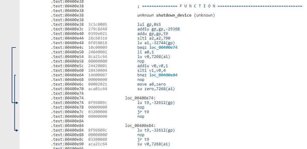
Apparently either zero or some word v0 will be stored to 7268, depending on which branch is chosen.
Could this already be some memory address for GPIO?
At evening I will prepare image with all enebled gpio in pinmux. This might be helpful.
GPIO4 is used for flash SPI:
https://www.electrodragon.com/w/images/3/34/MT7620_Datasheet.pdf -> page 23
Images with enabled all unused gpio in pinmux:
GPIO 4 was probably not the best example since that is indeed SPI, and also GPIO 7-10 didn't work either because of UARTF (however I still had them in my experimental GPIO list from half a year ago, when they were still unused, so I wondered what was different now).
Turns out even the other GPIOs won't change anything when setting them as output to be either high or low.
So I flashed back to the image from May 3rd to check GPIO 7-10 again, but also no success.
So it must be something directly in the SoC registers...
Also noticed that when the slider is switched to Off before sysupgrade, the device will eventually switch off after flashing has finished - actually that is when the reboot command will be issued!
And indeed - when the switch is set to Off, executing reboot will shutdown the device within 1-2 seconds, drawing 0 mA. (In idle mode it's almost 300 mA at 4.1 V btw, when it's busy it will be around 350 mA, without WiFi).
There's no devmem in this build of busybox, but I wonder what exactly will cause the shutdown:
Is it enough to disable DIG_LDO_EN in register PMU1_CFG (page 41) or does it require full SoC reset (SYS_RST in RSTCTRL, page 26) ![]()
So I am not even sure if this is victory or giving up now, it just feels like both at the same time... ![]()
Obviously, I forgot to check all the input levels of GPIOs for when the switch is set to Router vs. Off...
I think the bootloader / stock firmware will be reading (maybe listening by IRQ?) some GPIO that tells it when to shutdown, since the shutdown will happen immediately, even in between the 3 seconds interval for battery update from MSP. But apparently all it takes now is to declare some GPIO as button that will be polled by OpenWRT just like the others, which will be configured to execute reboot.
Maybe I'll check again tomorrow ![]()
(To be honest, I also somehow like the idea of switching off the status LED and thus having some NSA-style unsuspicious-looking off-the-shelf WiFi device that seems to be switched off to anyone looking at the power switch, but really it might be just be running wps attacks on all routers in the neighborhood or whatever... ![]()
![]() )
)
My next project will be finishing DCH-G020 support I guess, anyone happen to own some z-wave devices? ![]()
d'oh...
So I tried reading all available GPIOs from 18 to 45, no change based on slider switch.
Flashed back to old image from May, GPIO 7 to 10 - no change either.
Two pins I could not export:
- wonder what is the purpose of WDT_RST (GPIO#17) ?
- what about GPIO#0? It was observed to reset the device when written to 1, but we didn't even exactly know why it would do that. Maybe we're not supposed to write anything to that pin in the first place, but just read...?
// edit: just read the last posts in the thread again,
I apparently forgot about your suggestion from two days ago eventually when I was distracted by completing the schematic...
// /edit
So, last thing to try before throwing this device in the garbage:
Flashing back to very old image from April 27th, where no GPIOs are set, no LED flashing on boot...
Export GPIO#0, value reads as 0 when switch is in "Router" position.
Switching to "Off" position - ssh connection abort.
Holy crap, we didn't need to do anything, basically forget about the whole conversion from last 7 days, and just remove GPIO#0 instead... ![]()
Lesson learned - if you don't know what it does, just don't touch it! ![]()
As we would say in German, sometimes you can't see the forest since there's too many trees in the way...
Whatever this pin does, it's definitely not connected to Q6.
And actually I don't even care what it does to be honest... ![]()
By the way, is there any means of tristate configuration within the .dts file? Or would I just export the GPIO in the same way, but declare it as input, and then just set the direction register at runtime accordingly?
		stealth_mode {
			gpio-export,name = "secret_nsa_stealth_mode_enable";
			gpio-export,input = <0>;
			gpios = <&gpio0 0 GPIO_ACTIVE_LOW>;
		};
Just one more little OCD nitpick before building the (hopefully) final image:
Could you match the capitalization of the model name to be uppercase here?
I think it's in model = "D-Link dir-510l"; on line 10 of the dts.
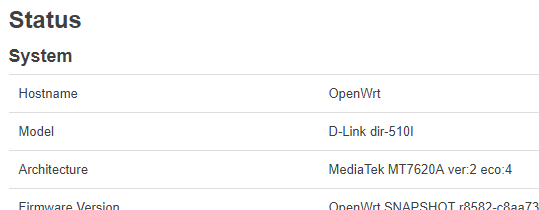
sorry for offtopic, just noticed MT7620A in this board is ver:2 eco:4 @daniel might be interested as he was looking for revisions of the chipset other than ver:2 eco:6.
also little googleing reveals DIR810L use ver:2 eco:3 and some unknown evalutation board use ver:2 eco:2 ->https://www.right.com.cn/FORUM/archiver/tid-161906.html?page=65
weird, sysupgrade from April version to latest got reset working in a slightly different way than anticipated:
...
[    1.103486] spi spi0.0: force spi mode3
[    1.111948] m25p80 spi0.0: mx25l12805d (16384 Kbytes)
[    1.122114] 3 fixed-partitions partitions found on MTD device spi0.0
[    1.134774] Creating 3 MTD partitions on "spi0.0":
[    1.144318] 0x000000000000-0x000000010000 : "jboot"
[    1.154978] 0x000000010000-0x000000210000 : "recovery"
[    1.166087] 0x000000ff0000-0x000001000000 : "config"
[    1.177582] libphy: Fixed MDIO Bus: probed
[    1.195281] gsw: setting port4 to ephy mode
[    1.203670] mtk_soc_eth 10100000.ethernet: generated random MAC address a2:f7:42:7f:f8:ff
[    1.220059] mtk_soc_eth 10100000.ethernet: loaded mt7620 driver
[    1.232503] mtk_soc_eth 10100000.ethernet eth0: mediatek frame engine at 0xb0100000, irq 5
[    1.249515] rt2880_wdt 10000120.watchdog: Initialized
[    1.260819] NET: Registered protocol family 10
[    1.273330] Segment Routing with IPv6
[    1.280816] NET: Registered protocol family 17
[    1.289738] 8021q: 802.1Q VLAN Support v1.8
[    1.300703] VFS: Cannot open root device "(null)" or unknown-block(0,0): error -6
[    1.315686] Please append a correct "root=" boot option; here are the available partitions:
[    1.332338] 1f00              64 mtdblock0
[    1.332343]  (driver?)
[    1.345371] 1f01            2048 mtdblock1
[    1.345375]  (driver?)
[    1.358390] 1f02              64 mtdblock2
[    1.358394]  (driver?)
[    1.371407] Kernel panic - not syncing: VFS: Unable to mount root fs on unknown-block(0,0)
[    1.388722] Rebooting in 1 seconds..
did something go wrong while flashing, or could it be due to some incorrect cached kernel command line during build?
will try recovery 
// edit: same again, image has correct size but mtd part for firmware is missing
My bad. Please try this:
nope, still the same.
I assume that mtdsplit_jimage_of_match_table allows to use a dynamic layout based on actual kernel image and squashfs, rather than using fixed lengths, while still being compatible to jboot?
I see no difference in
		partition@210000 {
			compatible = "amit,jimage";
			label = "firmware";
			reg = <0x210000 0xde0000>;
		};
compared to you changes for the other devices in the branch.
Maybe try make distclean to make sure at least nothing is cached that shouldn't be?
I'll be back for testing around midnight...
I still not sure where is the problem. I make distclean and rebase to master git. New images:
Code:
Maybe someone will see the problem.
Image: booting 
LuCI: not available because master branch
Power switch: well, not exactly working...
Difference to very old version? Back then, we had no GPIOs exported at all.
However when I
echo "1" > /sys/class/gpio/usb_enable1/value
the power switch will work.
This pin is active low, so I guess gpio-export,output = <1>; in the .dts will respect that and pull it low when kernel boots. However the value in /sys/class/gpio/ will refer to the actual line level instead, not the abstract logic value?
As far as I recall, USB ports really could be switched on/off independently, and it worked great with the pin definition we found. Now I wonder if / how we can have both ports enabled at the same time while also having the power switch work.... 
Maybe it needs some tristate / internal pull-up / pull-down / etc. configuration or whatever.
GPIO#0 will always read 0 btw, independent of the switch position.
Trivia: Apparently we're also voiding the FCC certification of the device by allowing arbitrary USB devices to be connected to both of the ports... 

@timg11 @xabolcs If you also have the device, could you try the latest image for some further testing? Everyone will use the device differently, so if there's still any hidden tiny bugs, I could probably not find all of them for sure
It will not brick the device, you can flash back to vendor firmware at any time by holding reset during power-on, and you don't need to open the device and detach the battery anymore to switch it off, just send reboot over ssh after setting the switch to Off (or write 1 to usb_enable_1)
I have DWR-116 where the OpenWrt support of these JBOOT devices started!
I'm just following @CHKDSK88's work, nowadays. ![]()
I added GPIO with initial state 3V3 and active low function:
If "active low" is set, logic is inversed. '1' male 0V and '0' make 3V3.
Fortunately we are in Europe. ![]()
I hope, that is the last change. ![]()
Could You tell me if gpio "usb_enable1" and "usb_enable05" are working correctly?
USB 0.5A working, USB 1A port disabled by default, reset switch not working.
Writing "1" to usb_enable1 while power switch is in Router position will cause reset, similar to GPIO#0, I guess this rather forces the reset by shorting some supply lines than being intended for resetting the device this way... but this also happened once when playing with yesterday's image).
So the pin should probably be set to input (got "Permission denied" when trying), but then we could only use one port and have power switch working, or activate the second port for "stealth mode".
Maybe GPIO#0 could be some enable pin for either the USB hub or some voltage regulator (5V? as the issues are apparently related to USB somehow).
I can not follow the trace, MT7620 is BGA on this device, so the pin could come out of a via basically anywhere on the pcb, and when the changing the output value things will happen that don't let you measure it anymore...
Does anyone know about other AMIT devices that have a battery? They probably didn't reinvent the wheel for this one, also found a cheap DIR-506L on ebay (kind of the predecessor of DIR-510L), waiting for it to arrive...
I'm actually also busy with other things that piled up in the meantime, so maybe this will need wait until after Christmas, though it will probably be to late for the 19.01 branch then.
Maybe we should ask this guy for help with ripping apart the binaries to shed some light on it (so cool how he hacks so many D-Link devices without even owning them) 
Maybe there is something like a multiplexer and state of both gpio is important?
The rabbit hole goes deeper...
USB 1A Port is connected via Charging controller from TI:
http://www.ti.com/lit/ds/symlink/tps2546.pdf

Looks like CTL1 is on ground (connected underneath the chip, thus resulting in the weird pad shape) and EN, CTL2 and CTL3 are connected somehow (one of them through Q1 on the other side), maybe two of them could be usb_enable_1a and GPIO#0?
USB 0.5A Port has a more simple switch that I could not identify:
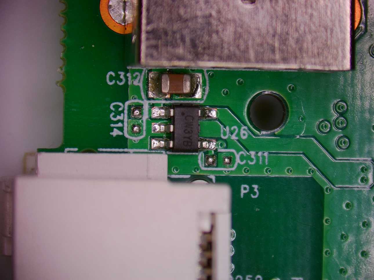
I thought they would use the USB Hub Control Pins to enable / disable ports, but apparently they just switch off the power. Or maybe both?
Data lines for both USB ports go through transformer (similar to ethernet) coils U1 / U24
Can You check with multimeter?
It look like transistor or simple switch. I agree. ![]()
Can You check uart (MSP <-> MT) before and durring shutdown on OFW?
Maybe MT7620 send command to MSP.
Checked last week, there was nothing (except level dropping when MSP goes off).
There is no such thing as a shutdown command, basically the device not shutting down must be some parasitic current that will keep MSP supplied via some GPIO input pin even after VDD (U19 regulator) is already switched off, apparently MSP controls the voltage regulator for MT7620 which would not switch off as long as MSP output is still on some weird level above GND...
Problem is, you can only measure on one side (USB charging controller), MT7620 is BGA, and after changing the output state of the pin something would happen that keeps you from making measurements (reset, power off, ...).
So I tried writing a little script gpio_noiseburst.lua that would allow for very fast switching between high-impedance and very short pulses of driven output, encoding the GPIO number it is currently writing to within a burst of 5 bits + 1 start bit for oscilloscope trigger. So the pin would never make a full transistion (thanks to pull resistors and line capacity), but there would still be enough "noise" level visible on the line so that you could decode the ID of the current GPIO after setting the oscilloscope trigger level close to either high or low level (whichever is the default of that line in high-impedance state), without causing reset or other undesired behaviour ![]()
e.g. GPIO#11 would be written pattern 101011
gpio_start = 0
gpio_end = 20

for pin = gpio_start, gpio_end do
  os.execute("echo '" .. pin .. "' > /sys/class/gpio/export")
end

function sleep()
  -- this is ridiculous
  count = 123
  while count > 0 do
    count = count - 1
  end
end

function moresleep()
  count = 1000
  while count > 0 do
    sleep()
  end
end

while true do
  for pin = gpio_start, gpio_end do
    os.execute("echo '0' > /sys/class/gpio/gpio/gpio" .. pin .. "/value")

    -- set "left bit" (burst start) for trigger
    n = pin + 32

    for i = 5, 0, -1 do
      exp = 2 ^ i
      if n >= exp then
        n = n - exp
        -- write single pulse
        os.execute("echo 'out' > /sys/class/gpio/gpio" .. pin .. "/direction")
        sleep()
        os.execute("echo '1' > /sys/class/gpio/gpio" .. pin .. "/value")
        sleep()
        os.execute("echo '0' > /sys/class/gpio/gpio" .. pin .. "/value")
        sleep()
        os.execute("echo 'in' > /sys/class/gpio/gpio" .. pin .. "/direction")
      end
      -- inter-pulse interval
      moresleep()
    end
  end
end
But I'm eventually giving up now...
- there's no usleep in lua or busybox
- tried installing luasocket ( +dependencies) to abuse for usleep but module would not be recognized (wrong version due to manual install?)
- flashed back to April image (no GPIOs exported), have fun with jboot upgrade process again, but no lua in old version (because no LuCI), installing did not work, it tred to download stuff from old lede repositories, manual install of current version of dependency liblua failed
- flashed back to current image, but can not unexport gpios, thus can not change direction
- no free gpios to even check whether the script will run at all, and calibrate sleep
- too lazy to stash current work on ar71xx stuff and build image myself

Could you build a current image with lua and without any GPIOs enabled?
Also, maybe someone should make a fancy c program gpio_noiseburst.c for lazy messing with gpios ![]()