Since you have two ports connected to the CPU, you do not need to tag on the CPU part, but you must reconfigure your networks.
And about your questions:
You only need to tag on the CPU ports because you defined your interfaces on the tagged devices.
Your router has a 7-port internal switch. One port is labeled as WAN, four are labeled as LAN, and the last two are connected to the CPU as eth0 and eth1.
Only because you configured it like that on the switch.
Because you defined the interfaces on the tagged devices.
Nope. But since it was there right from after the installation, I thought it might be needed by the system itself (just starting to learn openWRT).
Are you saying it can be safely deleted?
From your answers on 1, 3 and 4 I understand, that I overcomplicated the setup and there is a simpler way to tag the "internet port" with 201. But it still eludes me what exactly I did wrong and how to correct it.
AFAIK on devices with multiple CPU, each VLAN needs to be tagged on each CPU.
And on a default OpenWrt install/config: VLAN 1 is LAN, and VLAN 2 is WAN. Both are used by default, and both VLANs are untagged.
If your ISP however requires you to have a "VLAN tagged" on your WAN port (i.e. Deutsche Telekom with DSL requires VLAN 7; and yours require VLAN 201), then you have to set the VLAN to tagged on the (WAN) port.
But I still do not understand what CPU (eth1) and CPU (eth0) have to do with tagging the WAN port with 201.. My mental model around this topic obviously has some gaps. And I'd appreciate any pointers to any materials which would explain the meaning of CPU (eth1) and CPU (eth0) ports and why they should be tagged for all VLANs on the switch.
Yeah kinda tribal knowledge. I'm no field expert but my mental model is kind of: "the CPU needs to be able to differentiate each VLAN from each other". And if, for instance, one CPU is handling RX and the other CPU is handling TX of a NIC, then each CPU needs to be able to differentiate each VLAN from each other, so each packet needs to be tagged while cycling internally around. If this makes somehow sense to you
(Once upon a time I raised this question and someone explain it like: Back in the days and still with these plastic routers, you do not have dedicated network cards which could be bridged together, but only a single "switch". So, to even enable the usage of LAN and WAN we have to use VLANs to sperate the packets internal. So, VLAN 1 for LAN, and VLAN 2 for WAN, even if we will never transmit "tagged" packets out of a port/network interface...)
With my "explanation" from above, your question is maybe answered? If not we could kindly poke^W ping @jow because most of the time he is kind enough to explain it for like the 1000. time...
I appreciate you sharing your mental model with me. But still, I can't say it has "finally clicked" with me
That'd be awesome. B/c the original post is not so much about how to just set it up correctly (even though, to some degree it is), as about fixing my mental model and building the complete picture of what is going on
There are two paths from the switch to the CPU so that there isn't a possibility of bottle-necking that might happen if packets going in on WAN to get routed then back out to the LAN had to share a single path operating at 1 Gb. Inside the C7, the switch and the CPU are separate chips, and the two switch to CPU links are separate sets of wires on the circuit board. This is really only a theoretical concern here since this particular CPU core isn't fast enough to route at 500 Mb without a whole lot of proprietary optimization for speed that is only in the stock firmware.
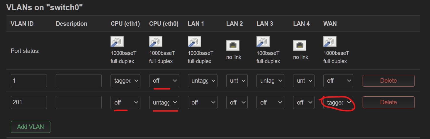
Keeping to that philosophy though, use eth1.1 for LAN and eth0.201 for WAN. It's redundant to switch both networks to both ports, so set the switch to "off" on the CPU port that is not used for that VLAN.
And it also works. The original question still remains, though I.e. why both CPU (eth0) and WAN have to be tagged in my setup?
@eduperez suggested that something was off with how I set up interfaces and devices.. But unfortunately I didn't completely understand how he suggested that should be fixed.
The ONT requires tagged packets. Thus wan is set to tagged.
Technically since there is now only one VLAN passing to eth0, you could make eth0 untagged and use eth0 (without a VLAN number) the wan Device. The switch would accept untagged packets from eth0, tag then 201, and send them out tagged on the WAN physical port to the ONT. But there is no performance advantage in doing so, and it breaks up the structure to add more VLANs later.
Another thing to keep in mind is that the switch chip can either remove or add VLAN tags, but it cannot rewrite to a different VLAN number as a packet passes through. Inside the switching matrix (between the input and output ports) the packets are always tagged and must have a unique number.
Now, the final part of the "mystery" I'm struggling with
You mentioned that there is no advantage in setting up tagging on 'bare' eth0 device. Does that mean that the original way I had it set up was okay/recommended one?
What it the special role of the two CPU ports (eth1 & eth0)? I.e. it appears that at least one of those must remain 'on' (either tagged or untagged) for a given VLAN. As if I turn off both, I either just lose Internet (when eth0 is off for VLAN 201), or LuCi fails to apply changes and eventually reverts them (when eth1 is off for VLAN 1).
EDIT: Just re-read your explanation from previous post:
It essentially answers my question #2 from the above. Thanks again!
i can not remember when and how but I believe I have read it in the wiki and here too
I would say either it is needed on every soc with multi cpu or it is not.
Ah kids these days with their fancy toys... Multi cpu and more then 32 MB of RAM... Pfffff