I can access the LuCI via 192.168.1.1 when it is connected via ethernet. I can also ssh into it when the ethernet cabe is plugged in.
The OpenWrt software is too complicated for me. It seems very difficult to set this device up as an extender.
How can can I reinstall the latest factory firmware? Is there any way to do that without soldering? and if soldering is necessary, can you point me to the best page for that please?
Thank you from a newbee that made a noe deeply regretted mistake,
you will be happy with you OpenWrt powered device.
If you still want to revert to stock firmware let me know, we will need to modify the image file, will be more difficult than configure your device as extender
"This is one of method to back to stock firmware, Second method is use my "back_to_stock" firmware like sysupgrade file. You can use LuCI ( system - firmware upgrade) or ssh command line ( sysupgrade -f back_to_stock.bin)"
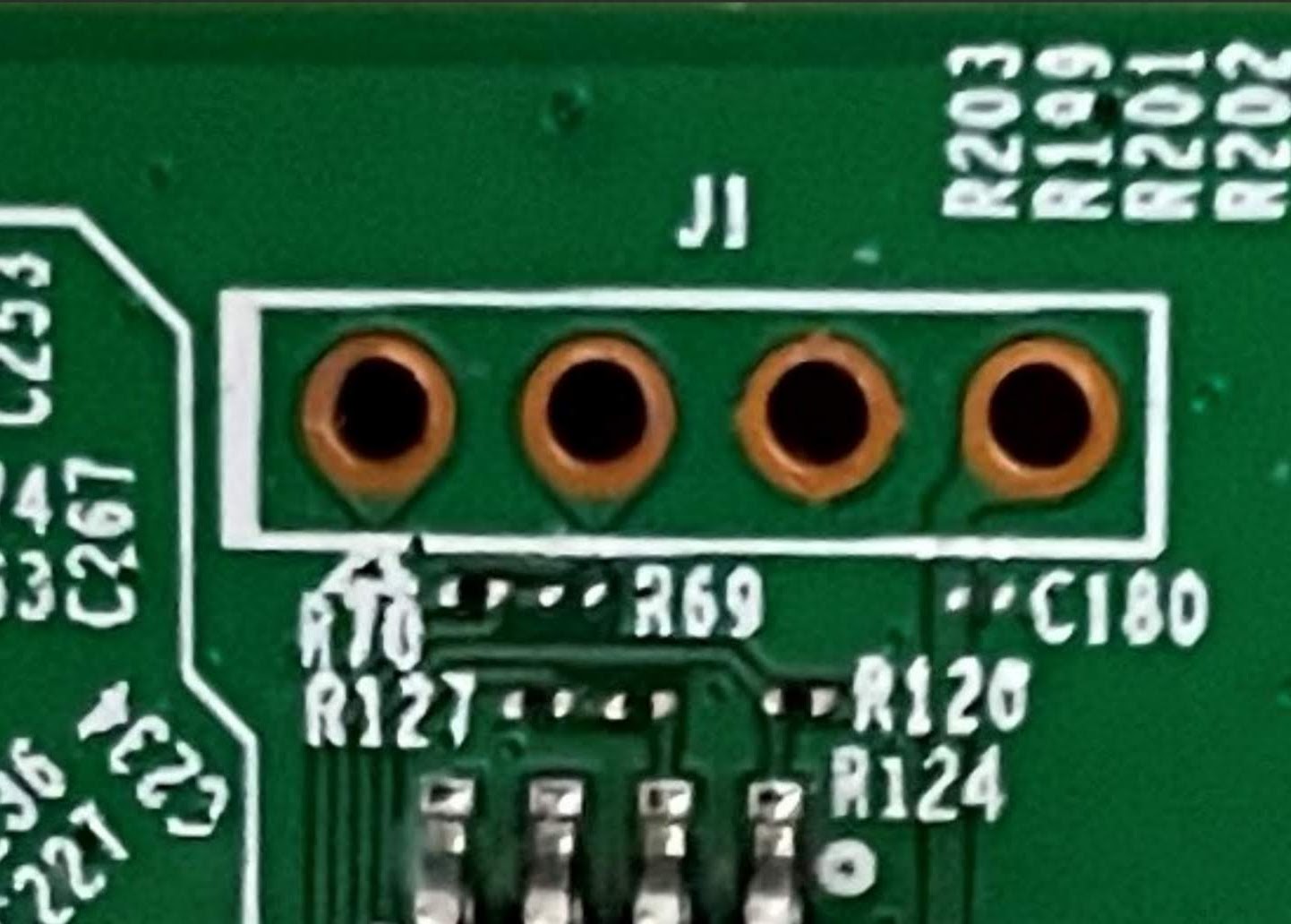
After that the RE450 is now completely dead. All LEDs are dark. The reset button (pinhole) no longer resets anything. I opened the case. The solder pads no longer exist in V2. There are now four throughholes that probably provide the ability to solder in pins to attach the TTL serial adapter. But what is the order?
I am really upset with myself. Should have waited. I succesfully worked with custom firmware before and also flashed .bin files onto chips, but with RE450 I failed.
Is there any way to recover this device? If I now probably need to solder in the pins and flash firmware I need more details than in Heinz's post. I don't quite understand the use of TSFTP here, when using a USB TTL adapter. Shouldn't I upload the firmware through some uploader tool or an IDE (I do this regularly with ESP32 or Atmel chips). My understanding was that the TSFTP method - that uses an ethernet cable - doesn't work here and therefore I needed to solder and use a USB TTL cable. But perhaps I got it all wrong.
Anyway, without your advice I just created a pile of electronic junk I am affraid.
don't worry, can be fixed, tftp basically involves on running an exe that tries to provide a file to be download by the bootloader.
the usb-ttl adapter will allows you to have a telnet like access to the device, and while booting you can see the errors found (tipically bad magic number for firmware) and stop the booting process and run some commands to download a new firmware using tftp.
if you need I can help you with that, I've done some unbrick recoveries in the past when I was new on the topic.
start taking highres, hd pictures of the board and post them here, or link me to pictures of that device board.
I see something that could read J1 and a small triangle that could be the TP1. According to Heinz this would be order for the serial connection then?
JP1 - Tx (triangle?)
JP2 - Rx
JP3 - Gnd
JP4 - 3v3 - leave not connected?
For gnd you can test is using rhe continuity probes of a multimeter. That is the safest. Or with a very good zooming at both sides verify if the pin has connection to the ground of the board (usually has 4 lines like a cross connecting the circle and the rest of the board)
Then you don't need to connect 3.3v
And while booting your board you can connect either the tx/rx (if you dont know which one is which) one by one until receive text on the screen (that will be your tx board to rx ttl connection) and then use the other cable and try to send a key and see if you see it on the screen).
But sometimes you just find using google and someone else have already found the actual pinout for the board and you can skip those steps.
Then all depends if you use windows you can use putty or minicom/screen on linux... To connect to serial-ttl.
Yes. Seems to be right. Third one has that cross to gnd. And the last one has a bigger (for voltage) line.
If doesn't work you can just switch 1 and 2 snd retry.
I am still struggeling with what I would do with Putty (ind Windows)? I am using putty all the time to connect to my raspberry PIs, but what would be the settings for using it with a USB TTL cable and how do I transfer the firmware? This process here: https://www.youtube.com/watch?v=ZW5fpOWpI0I does not work with teh RE450 (this was mentioned in the OpenWRT forum several times).
VERY HELPFUL! I now understand, what you meant with the PCB lines. Will solder in pins and test the TTL connection via putty. Maybe no today, but sometime next week or weekend. Need to work now. Will keep you posted, how far I get with the serial connection! Greetings to Buenos Aires.
Could not resists and tried it. When I power on the RE450 all blue LEDs flash briefly once. Then they are dar. I started the unit with the reset button pressed, without the button pressed, with the reset button pressed the moment the blue LEDs flashed: no luck. I swapped the Rx Tx lines. I used Putty with the COM port selected that the USB TTL was attached to. I am unable to enter this "magic mode", where the device is looking for the firmware. I am affraid that the RE450 does not behave like the other TP link products: https://www.tp-link.com/fr-be/support/faq/844/