TL-WR842N Hardware Upgrade project

Hi,
I got hold of this chinese router TP-Link TL WR842N hardware version 4.1. This is a learning project. This board got 1MB flash and 8MB ram. I know it is not good enough for Openwrt.

I want to increase its flash and ram. I got all the materials required for it.

The first target is to get hold of serial debug port which seems to be deactivated.

This baord is similar to TL-WR841ND v9.0/v10.0 as shown here

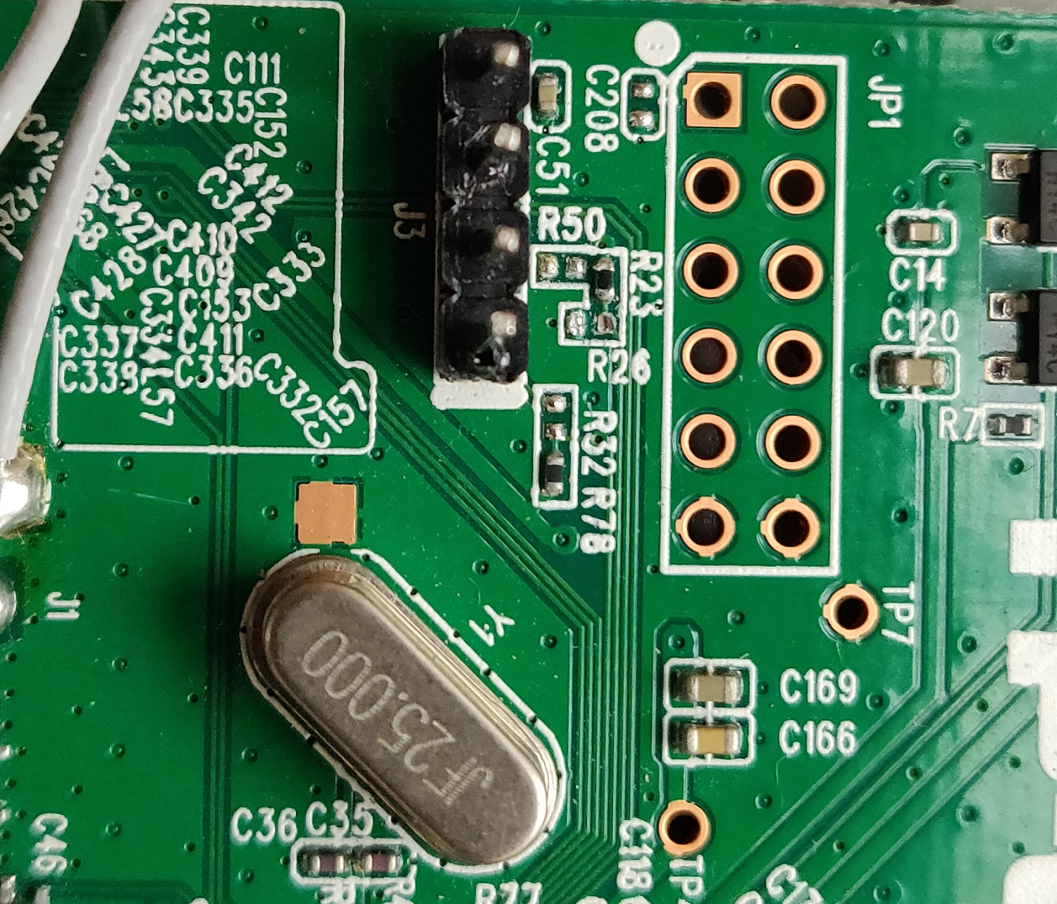
There is a tip to remove R26 to activate serial debug. But after removing R26 the port is still silent.

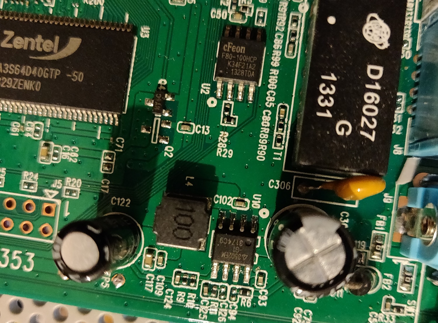
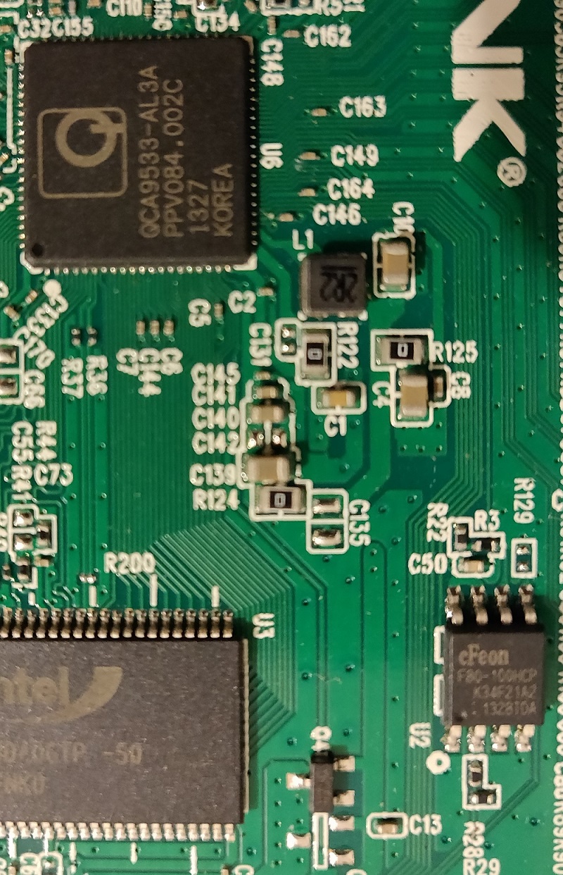
The router board and devices attached to are shown in the images.

Sorry! I can post only one image. in one post.

Any help to get debug serial activated will be much appreciated.

Thanks

This is the image of flash chip and RAM.

And this is Processor.

Would you post detail of serial port and cpu ..??

Which cable you have ..??

Sorry. I forgot upload serial port image. Please find it attached.

Hi,
Thanks for your response. I have uploaded the image of serial port.
This is what I have figured out. 3.3v volts can be seen trough meter when connected to 3.3v pin and GND pin.

CPU info is the same as in the above link. I believe it is exactly the same as V9.0.

I am using a USB TTL device to attach it to the serail port of router.

Let me know if you need more info.

Thx

Your circuit board not identical 841 v9/10. hardware is same.
You've soldered serial so it doesn't look very clear, maybe need to short R50.

OK..
put back R26 and short R50 and R32 .. or use any resistors (average 10ohm - 1k)

Which usb-ttl device ..?? .. marker or chip vendor ..?

I have good experience with PL2303 chip ..
like this: https://www.ebay.co.uk/itm/USB-to-TTL-Serial-Port-PL2303-HX-3-3V-5V-Module-Adapter-Cable-Board-500mA-UK/272758761168?hash=item3f81b066d0:g:jlUAAOSw-ldZZXbo

..it is cheap chinese clon, but working ..

Yup. I am also using PL2303.
As for putting back R26. This is a bit of work. And I need to buy resistors. I will let you know when I have done it.

When you say short, you mean make the connections direct. Right?
Thanks again for response.

Yep, connect direct two solder point at R50/R32, not need using resistor.
For safety, use multimeter to measure the continuity from RX/TX to R50/R32 to know which pins it connects to.

And remember, don't connect 3.3v pin from board to uart adapter.

...
forgot for R26, it is pull-up resistor ...

just try to short R50 and R32 ..
temporary with piece of wire or with tweezers
..
you can see somethink in terminal ..

1 Like

Sorry guys. I messed with the board. I think the soldering gun was too hot for these delicate connections on the board. The copper connentions came off the board and now I can't short the connections.

I am very grateful to you for your kind help. I got another Tenda F3 modem but it power connector is different. I have ordered power connector and as it arrives I will let you and ask for help.