Support for GPON SFP FGS202

Hi Louis42

Option 1:
Remove the chip completely. Attach soft wires to all pins. Read/Write. Solder back.

Option 2.
If I understand correctly Rixo does in-circuit reading without the chip being removed. Pin #8 (VCC) needs to be lifted/separated to prevent current from flowing back into pcb.

Option 3.
Same like option 2, except use self-made clip for the WSON package.
Something like on the picture #5 or better https://imgur.com/a/ox4Ey

Hi Louis42, Hi Centaur,

Yes indeed, instead of lifting/separating PIN #8 everytime I want to read/write the chip, I separated and soldered a diode (PMEG3005ELD) between the capacitor and the PCB VIA of the VCC track to PIN #8. The voltage drop is around 300mV but this should be still in spec of the MX25L6435E. Now when I power the flash chip from my Flash programmer I won't power the whole module.

I think for using the clip in-circuit you still need to separate Pin #8?

Would it possible for you to do this also with the 0000000000 password?

I think it is best to flash your own goi_config to keep the laser calibrated: See also:
https://forum.mikrotik.com/viewtopic.php?t=116364&start=50#p751330
Is this encrypt_data string maybe calculated from the goi_config string?

I sent my FGS202 with in-circuit programming to the location I actually would like to use it. Hopefully I can debug it remotely.

Does the module also use the changes you write there, and are they still there after a power loss? I thought the PEB98036 is only emulating the EEPROM and the changes are not written back to flash.

I think for using the clip in-circuit you still need to separate Pin #8?

Yes, I wasn't clear enough.

Double checked strings this time. Not sure why I got different string before for 1's.
for 0's
f6483c31b2f03706ed04093ad576cc5750a31cafc0c4151d15bb539d86f69ca1

for 1's
ad1d98831ab2031f3836ac88b3f911014c716e63079bc50c49ee6d0f57fc8066

I think it is best to flash your own goi_config to keep the laser calibrated: See also:
https://forum.mikrotik.com/viewtopic.php?t=116364&start=50#p751330

Yes, it makes sense to keep the optical configuration specific for the model. Thanks for the link. Wow, full Openwrt, these modules are basically plug and play with a graphical interface. Something to consider as the next project.

Does the module also use the changes you write there, and are they still there after a power loss? I thought the PEB98036 is only emulating the EEPROM and the changes are not written back to flash.

Yes, the module uses the changes and they are kept even after a power loss. The encrypt string/syslog also gets updated.

Hello, Rixo, Centaur,

Thanks a lot for this information, I haven't diode here but I will try to desolder Pin 8.

Must I use airflow solder or only a iron solder ?

Hi Louis42,

It will be rather hard to desolder Pin 8. Cutting the trace between Pin 8 and capacitor should work better.

OK guys, I managed to get this module to work with my ER-X-SFP, this module act very strangely compared to other modules (maybe software bug?)

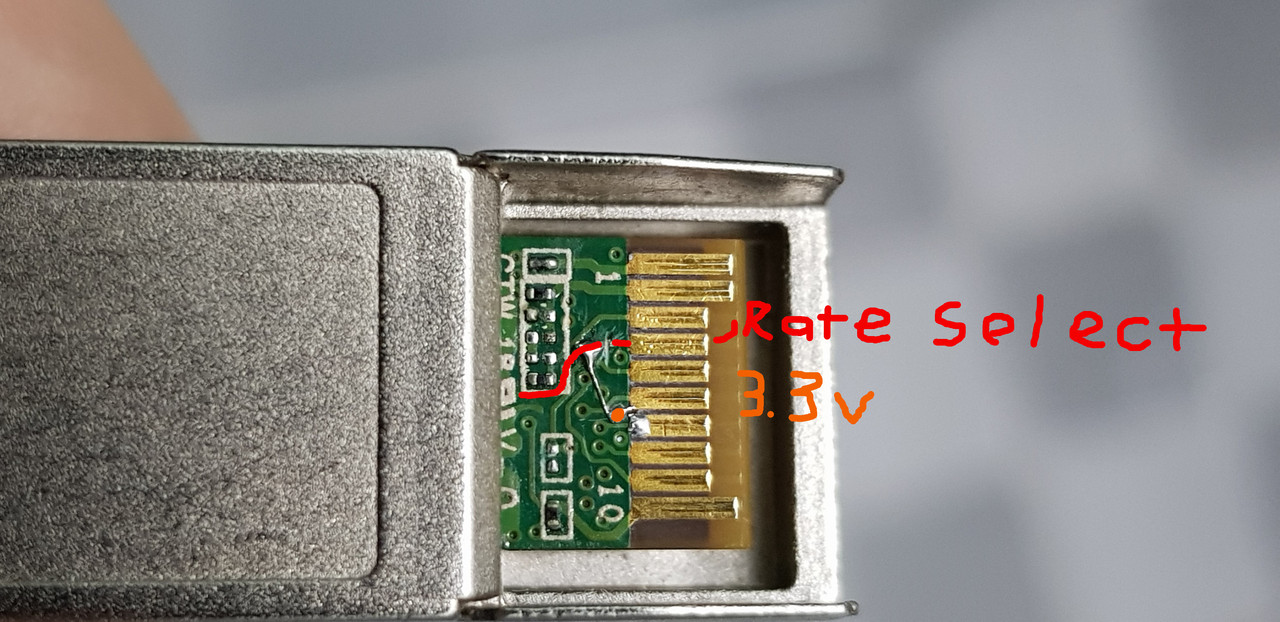
What you need to do is to pull the Rate Select/Pin 7 to HIGH, leave it floating or LOW will result in a reboot loop every 30s, in the pic above I've cut the trace to the contacts and bodged a wire to a via hole that connected to the VccT on the other side which should be tied to 3.3v, resulted is my ER-X-SFP has recognized it and I am able to dial PPPoE successfully (my ISP does not check GPON S/N or SLID), the module now also worked with the generic Chinese Qualcomm SFP switch, the link is detected and PPPoE worked fine.

If your router/switch leave the Rate Select pin floating then you can just tied it to the 3.3v and does not need to cut the pin... but the ER-X-SFP having it's Rate Select pin tied to GND so the only way is to cut it, I've asked UBNT and they said the pin is not able to control by software so it's a dead end on the ER-X-SFP side.

I also have received another FGS202 module which has English text on it, it also acted the same when you leave the pin floating so I think the two French and English text variants are the same, just relabeled for French's Orange ISP.

2 Likes

Hello Everyone!
Thank you all for your effort this post has helped me a lot!

I would like to also contribute to this effort in some way.
But in order to do that i need your help first!

can anyone please set the following strings as GPON Passwords:

GC87EA41D
GC87EA2DF
and send me the encrypt_data so i can analyse the connection,
Thank you all.

Hi borjan,

To my knowledge, GPON password should be exactly 10 alphanumeric characters long.
The encrypt_data string is firmware specific. The same password will generate different encrypt strings for various modules.
The password can be easily set by writing to A2h EEPROM table by using I²C programmer.

Hi centaur,

Thank you for the fast and helpful reply.

I did realize this by now but now i am having trouble writing the chip, i am using flashrom and arduino as spi programmer but the write is failing. I cant seem to get to the reason for this

Also the A2h table how can i access it? is it stored on the flash chip? where is it located in the flashdump at what offset.

Did you remove the flash for writing or isolate pin number 8?

We have no public information regarding detailed flash layout or mechanism of accessing it. In the post above I described which SFP pins to use for writing to A2h using i2c-tools.
There is also commercial SFP adapter available called sfptotal but is quite expensive.

Yes i did, i desoldered it completely and soldered wires on it. In the end i did manage to flash it. Now i need to do the i2c-tools from raspberry and see what i can do. I found the adapter but thats a very high price. Also how do you connect to the sfp module for i2c or uart? while it is in a port or removed? do you solder the golden pins?

If possible avoid soldering directly to the golden pins. In EU I got my SFP Molex connectors from digikey. Make yourself adapter for EEPROM programming, optionally second one for connecting UART USB console(not really usefull at this moment)
EEPROM adapter needs 3.3V power source.

molexsfp1

Some "Do it yourself" and cheaper SFP breakout boards.


https://shop.sysmocom.de/products/sfp-breakout-board-v1-kit

https://git.osmocom.org/osmo-small-hardware/tree/sfp-breakout

1 Like

Thank you very much for this valuable information! Now it is my turn, i specialize in binary embedded OS reverse engineering. There is a possibility to embed an ssh backdoor and a script to turn off the firewall in order to ssh via lan interface of the module. Flash must be read, the images extracted and edited then checksum redone and contents re flashed to the chip. I will keep you posted.

Many thanks. Let us know it goes. I can test it on live system and provide feedback if needed.

Hi guys,
Glad to find this topic, I am trying to use this module on Clearfog GT 8K, a ARM SoC with SFP+ cage.
I am running mainline linux (5.4.x) but when inserted in the cage, the link is not detected.
However, ethtool -m eth0 works and I can have info about the module.
Any idea how I can debug this further ? Should I try soldering PIN 6 like suggested ? Or disable autoneg on the interface with fixed 1G (speed is still 10G when inserted) ?
Thanks for your inputs.

Welcome johnk,

Soldering pin 6 to the ground will not hurt anything. The pin should be in a LOW state for proper module detection.

Another thing to consider is the state of the DyingGasp(Rate Select) pin. It appears that pin 7 on FGS202 must be in a HIGH state to complete the booting-up process.
I don't know how Clearfog implemented pin 7, but it's worth taking a closer look.

Please see the results of the minhng99 investigation.
https://forum.openwrt.org/t/support-for-gpon-sfp-fgs202/42641/47

Linux handles SFP modules via

  • sfp-bus.c [1]

    • probes the module's eeprom_id through EEPROM dump and mainly:

      • guesses and sets the port type
      • guesses and sets link modes
      • guesses and sets phy_interface_t mode
      • informs the SFP socket that the network device is now up, so that the module can be enabled by allowing TX_DISABLE to be deasserted
      • inform the SFP socket that the network device is now up, so that the module can be disabled by asserting TX_DISABLE, disabling the laser in optical modules

      Commonly it prints in the syslogs something like

      sfp: module Technicolor AFM0002 rev 1.0 sn U7L8C002676 dc 03-12-18
      sfp: SC connector, encoding NRZ, nominal bitrate 1.3Gbps +0% -0%
      sfp: 1000BaseSX- 1000BaseLX+ 1000BaseCX- 1000BaseT- 100BaseTLX- 1000BaseFX- BaseBX10- BasePX-
      sfp: 10GBaseSR- 10GBaseLR- 10GBaseLRM- 10GBaseER-
      sfp: Wavelength 1310nm, fiber lengths:
      sfp: 9µm SM : 20000m
      sfp: 62.5µm MM OM1: unsupported/unspecified
      sfp: 50µm MM OM2: unsupported/unspecified
      sfp: 50µm MM OM3: unsupported/unspecified
      sfp: 50µm MM OM4: unsupported/unspecified
      sfp: Options: txdisable, txfault, los+
      sfp: Diagnostics: ddm, intcal, rxpwravg
      sfp: SFP module encoding does not support 8b10b nor 64b66b

    If that probe fails the module will not work.


  • sfp.c [2]
    • performs state machine checks for signal status (asserted / dessarted) for RX_LOS and/or TX_FAULT

    • may print in the syslog:

      sfp: module transmit fault indicated

      relating to the signal status of TX_FAULT (tx-fault in hi IRQ), in which case tries to clear (recover) the fault fives times in total, pausing one second between each attempt and if successful (tx-fault in lo IRQ) prints

      sfp: module transmit fault recovered

      If the five attempts are however exhausted it prints

      sfp: module persistently indicates fault, disabling

      and as a result there is no WAN connectivity. Signal status detection is only attempted again if the interface is being restarted, else the link will remain a down state.


userland for debugging:

  • mii-tool is not suitable for modules that do not have a PHY; the “PHY” registers are emulated, and are there just for compatibility
  • ethtool is better suited and common go to
  • cat /sys/kernel/debug/gpio for modules with GPIO, debugfs enabled and being mounted
  • gpiodetect | gpioinfo from gpiod-tools
  • if the I2C GPIO expander is interrupt capable watching cat /proc/interrupts | grep sfp could help in debugging efforts

developer (R. King) currently looking after SFP.C development at Linux source provided this shell code loop routine to monitor the tx-fault signal state changes reported from the module to the kernel (eth2 being the CPU port facing the SFP cage in this particular node design).

ip li set dev eth2 down; \
ip li set dev eth2 up; \
date; \
while :; do
  cat /proc/uptime
  while ! grep -A5 'tx-fault.*in  hi' /sys/kernel/debug/gpio; do :; done
  cat /proc/uptime
  while ! grep -A5 'tx-fault.*in  lo' /sys/kernel/debug/gpio; do :; done
done

[1] https://github.com/torvalds/linux/blob/master/drivers/net/phy/sfp-bus.c
[2] https://github.com/torvalds/linux/blob/master/drivers/net/phy/sfp.c

1 Like

Wondering whether there is a difference between the (potentially subsided?) module provided by an ISP and one that is procured from independent vendors, or the pin 6 issue being a general violation of the SFP MSA instead?

Could not find a data-sheet for the module that exhibits the pin layout/definition but if indeed violating the SFP MSA it would explain why it does not work since sfp-bus.c and sfp.c adhering to SFP MSA conformity.

Supposedly it is not necessary to fiddle with the hardware but instead correct the respective GPIO line to change the offending pin for compliance. Probably gpioset from gpiod-tools will be useful for that purpose.


Incidently stumbled upon this blog [3] and there is no mentioning of needing to fiddle with the hardware to get the module working a in switch device, though not clear what sort of OS that switch is leveraging.


[3] https://vincent.bernat.ch/en/blog/2019-orange-livebox-linux

Hi guys,
Thanks for your valuable answers, this helped me a lot.
I finally got it working after hardcoding phylink to 1000baseX_Full in sfp-bus.c

There is a host up at 192.168.2.1 with ssh port open, however I could not guess any credential to authenticate.