Hello, my dear openwrt community.
I want to share with you my journy getting an unkown mpcie 4g modem to be my daily driver for my internet connection.
1- Background:
in my country most ISPs use band 42 LTE (3.5GHZ) this mostly (in my opinion) due to the the technology that was wildy used before LTE was WiMAX.
One popular ISP bundled a router(CPE) made by Gemtek namly : WLTFMA-135GN with their subscription plans, soon after they started to update to new routers rendering that router to be thrown as it only works as a CPE, thus got sold in bazars as cheap as 2$ , so I got my hands on 4 peices to find out that they are using an mPCIe 4G modem for connection.
I own a ZBT WG1602-32MB router that has support for dual mPCIe 4g Modems and dual sim slots, so I decided to use these mPCIe modems and makea load balancing system.
2- Problem:
when I inserted these unmarked unbranded mPCIe modems in to my openwrt ZBT router and installed the driver "CDC_ETHER" they got recognised and a single ethernet device was found ,3 ttyACM devices also added thus I was able to send AT commands on ttyACM0, OK nice it works I foolishly said to my self.
Now it is time to connect to ISP, BUT, even though the sim card was inserted it never got recognised:
AT+CPIN?
+CPIN: SIM NOT INSERTED
OK
so I needed the documentation for this Modem, but none can be found. There is no label , no marking on the sheilding of the Modem, which made it impossible to find any documents for it.
3- Starting hardware reverse engeneering
the first thing I noted that the gemtek router uses a 9 pin simcard holder , while my ZBT uses 7 pin holder, so this must be the problem why my sim is not found by the modem.
So I had an idea to use my multimeter in continuity mode to map the 9 sim holder pins on the OEM gemtek router to the mPCIe connector pins (sometimes I used ohm meter).
I repeated the same for the ZBT router and compaired the results.
what I found that on the 9 pin connector the last 2 pins are acullay not connected to anything
and all 7 pins on both devices match to mPCIe configuration except for 1 pin.
what does this pin do ??? after couple hours searching online for the 9 pin holder and the 7 pin holder pinout diagrams, I finally was able to deduce that this is the SIM_DETECT pin, which on further investigation on the gemtek router board is high (2.7 - 3.3 volts) when sim is inserted.
4- Solution:
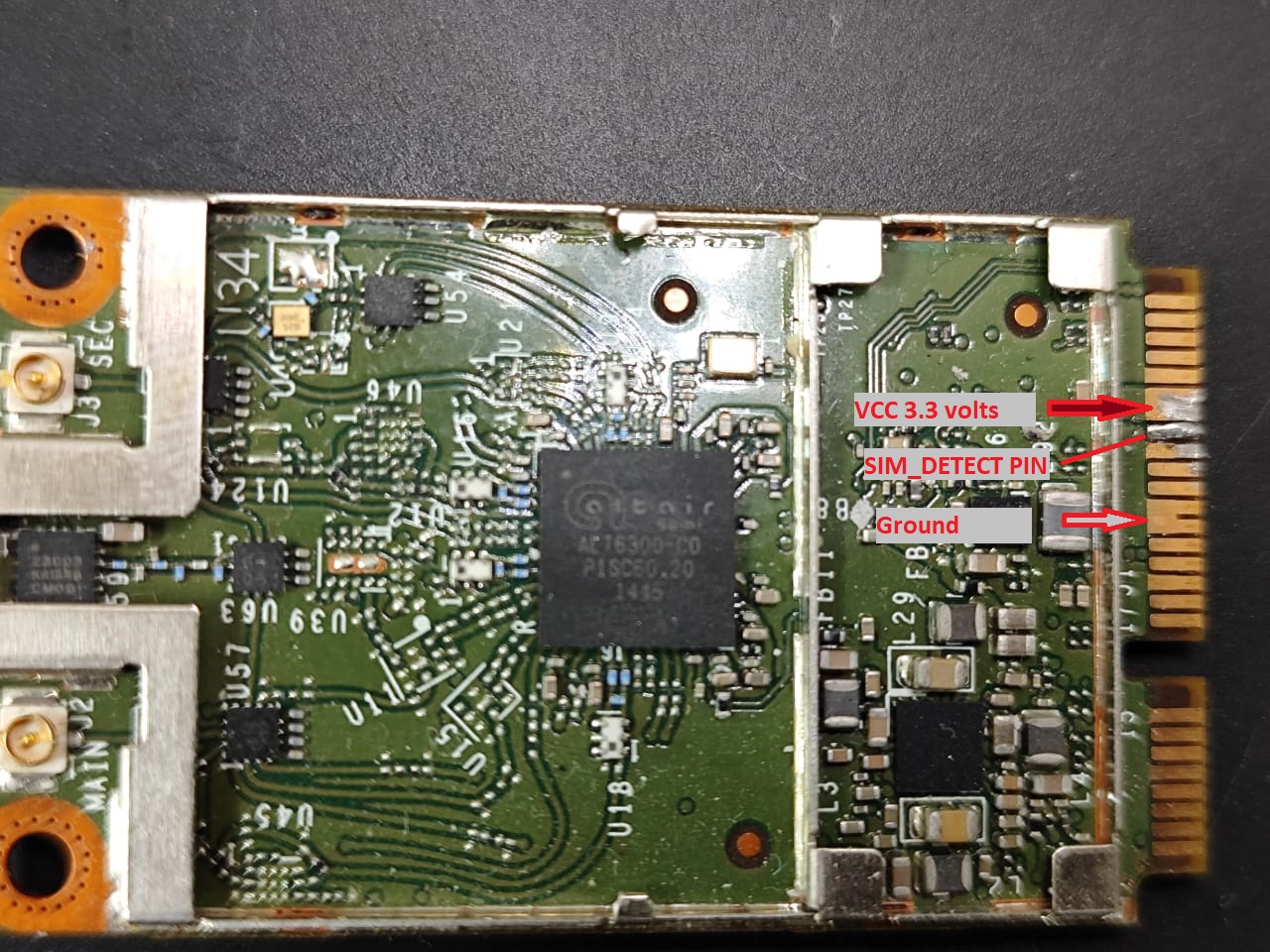
I soldered a 10 kohm small smd resistor between vcc and sim detect pin and since that pin on the mPCIe connector is wrired to ground I had 2 options 1- pluckout the mPCIe connector pin form my zbt or cover the modem pin with some insulator , I endedup puting some slicone adhesive on it.
AND NOW Moment of truth:
AT+CPIN?
+CPIN: SIM READY
OK
BOOM it worked.
I used standard AT commands to register, attach and connect to my ISP it worked very nice openwrt got an IP address and Internet is now live.
connected 2 modems and setup MWAN3 and load balancingis working nicely.
5- New Problem arrises (software):
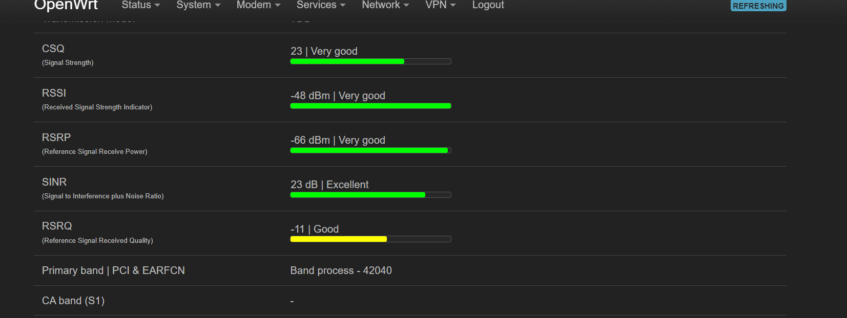
I need to see my signal parameters (RSSI, RSRQ, etc.) but how there is no documentation remember ?!
so I started to look online for 4g Modems running on altair ALT3800 soc and ALT6300 RF transceiver.
1 single hit was found for Mikrotik R11e-4g mPCIe modem which also does not have any public documentation . AHHHHHH!
Mikrotek:
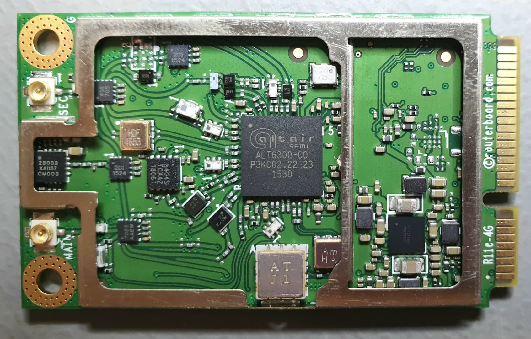
My Modem (UE):
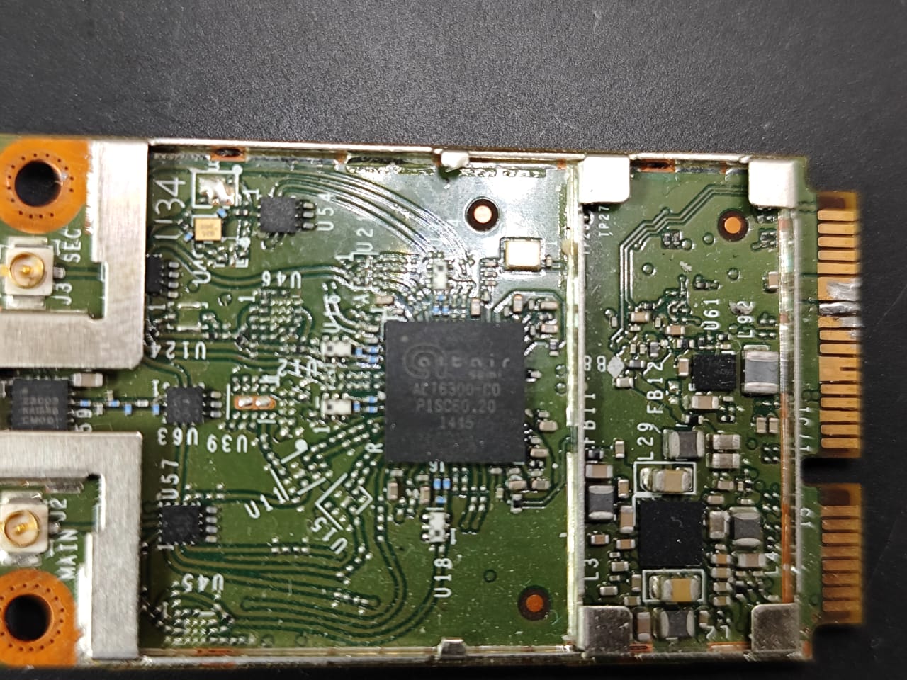
Very similar right ?!
The link has some very important AT commands one of which is :
AT%COLLECTLOGS
looking on the internet for that command yieled a leaked document for some propietery altair AT commands.
And I was able to dump the logs to my ZBT router and I found that the modem has the ip address 2.2.2.1 and it has ports: 80,7777,8888,9999 open.
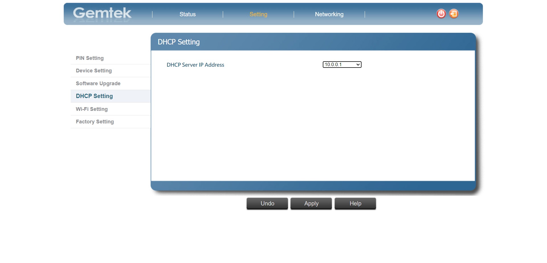
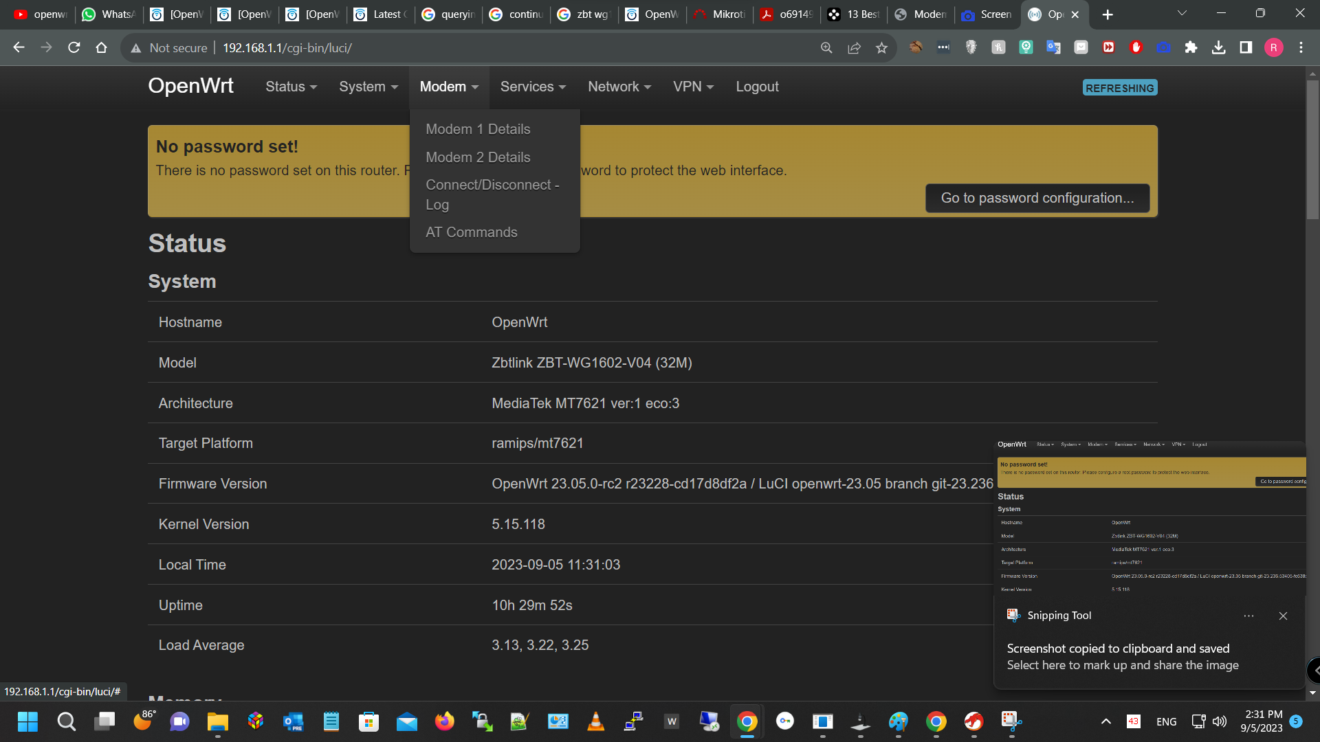
nmap was unable to tell me what services are running on those ports , well 80 is http server and gives access to very limited web interface, actually you can use it for 2 things only : restore to factory , change dhcp IP from 2.2.2.1 to for exmple 10.0.0.1 here are some scrren shots:

I was able to dump the OEM routers firmware and used binwalk to extract its root and I did a grep scan to the files found in it for any AT commands it uses for connction or signal querying but NONE WAS found even looking for scripts that use ttyACM0 also none except one that used ttyACM1 and it was for logs!!!
1 binary file peaked my attention ( lte_cm) so I poped this binary excutable file in ghidra decompiler and was pleased to find out it actullay does not use serial port for AT commands it uses TCP on port 888.
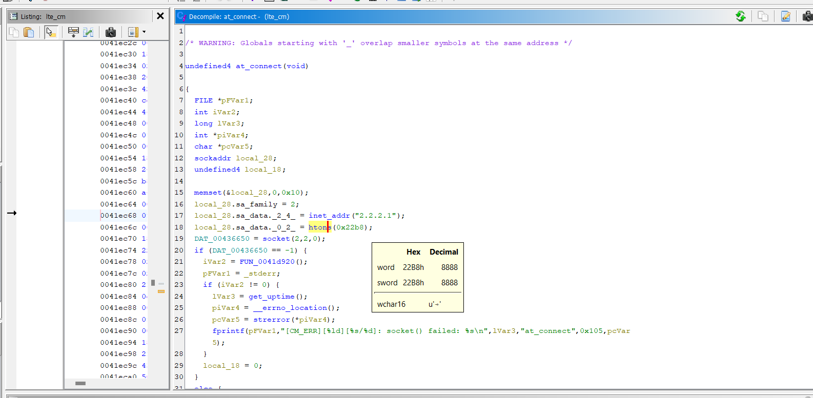
upon futher investigating the code I found out it does not send AT commands to modem at port 8888 but sends numeric codes , so I made a quick c# console app to connect to 2.2.2.1 at port 8888
and started sending numeric codes:
(client ) --- > 0 ( sim_status )
(server) ---> 0,4,READY (0 here is the code you send , 4 it means success, READY is the sim state)
now 1 numeric code allowed me to send shell commands to modem thus enalbing telnet and gaining access to shell
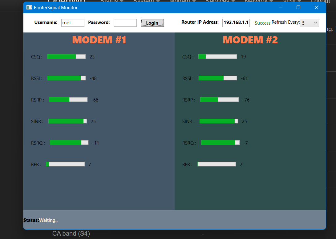
Ok I think I will stop here but I made a few apps to see my signal quality I will post some screen shots:
I still have some things to mention like bricking 1 and restoring it using UART without an mPCIe breakout borad and how I found the UART pins on the modem, may be a story for another time
P.S my .ipk for Luci to monitor signal status is based on luci-app-3ginfo-lite
Thank you for reading.