bricked during back to stock file installation from openwrt via mtd
no response from device both lan wifi nothing works
only all light flash for few seconds when power on.
tried
reset button. debricking steps without opening case tftpd. then opened case
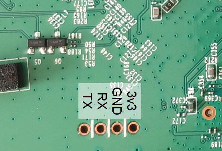
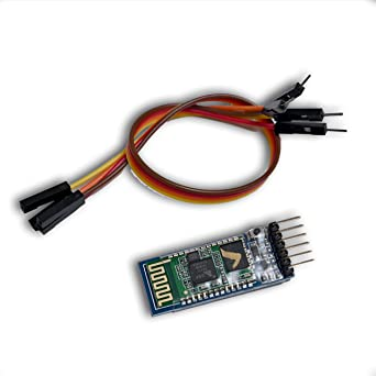
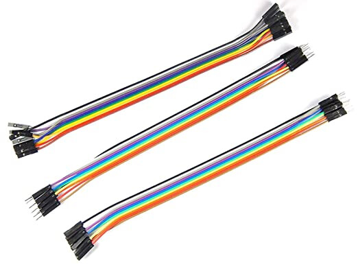
connected usb ttl adapter > 2.54mm jumper cable > 3 holes in pcb(gnd rx tx respectively)
You might try toothpicks or something in the holes to make sure there is contact. I've been successful without having to solder them, but it took some fiddling around to get contact.
The TX/RX markings are usually device-centric, so TX on the router would need to be connected to RX on the USB device and vice-versa.
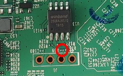
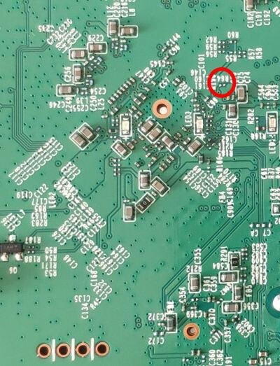
Do I need to do something with the red circled area in the above pictures. What are the " unmounted R64 & R69 0201 resistors/jumpers". Do I need them. I only got the 2.54mm jumper cable below
I'm sorry, I'm not familiar with that board at all.
One thing that I could suggest is that if you have a multimeter with an actual moving needle, you can see the serial output happening. Set it to measure 10VDC, and look between the GND and TX terminals as it boots. The needle should wiggle a little if there's anything being output to serial.
If you are sure that there is serial output happening some other way, then don't bother with this. I only suggest it because it isn't clear if the problem is the device, or cabling, or the usb serial converter, or the putty configuration.
Oh, and something else that should have been said much earlier -- make sure that the USB/serial converter is set to the proper voltage, in this case 3.3V. Some of those ship set to 5V.
I wouldn't bother with vcc terminal and power the router using it's own supply. The OP needs to make sure tx/rx pins actually connects to something on the board, a lot of times they're just left open circuit and a resistor/ jumper is needed to connect it. And from the looks of it, the RX terminal on router seems to be not connected to anything.
How do i know which of the two small metals to connect to which one.
From multimeter I figured out the rx tx gnd and 3.3 v holes.
now I can see gibberish output if I connect just two wires from gnd and rx of ttl adapter to gnd and any one of tx or rx both of them give random text for all the baud rates.
If I connect three wires to tx rx and gnd then no output.
I do not have a 0 ohm resistor can I solder it instead of using resistor.
I tried to solder the two pins r64 and r69 now all the four holes show high voltage 14v+ I think I might have shorted something. hopefully it's now damaged permanently.
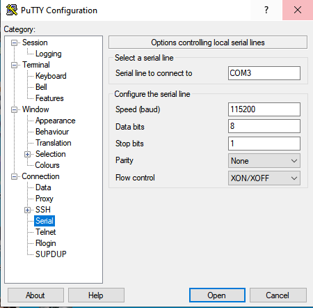
Serial parameters are 115200, 8N1. This should work for most devices or it wont work at all. This is also mentioned in wiki.
Well, something went wrong that's for sure. Even the device wiki says " Connect only GND, RX and TX, don't connect VCC (3v3)". Because, anything could happen when using that pin to power the board. Those are test pins for a reason.
14 volts doesn't mean it's shorted. If it were, something on the router would heat up. And it would smell bad.
needs unmounted R64 & R69 0201 resistors/jumpers Jumpers R64 and R69 needs 200ohm resistor (either smd one 0201 or through hole, red black brown). Find those resistors and solder them. Then try connecting to gnd, rx, tx without vcc.
115200, 8N1
This is the setting I use in putty, it's default. And it works.
If nothing works, then you can program the flash IC, that winbond one with 8 pins. You'll have to buy a programmer for it with IC clip. ch341 is the programmer.