Broadcom doesn't receive a lot love here, but feel free to search the forum for R7960P.
I've looked and it is only mentioned two times on the forum. One was about which routers have AES encryption, and another was when it was mentioned with the R8000P.
How would I add support for this router? While I am new to the coding scene, I’m willing to put the hours in if it means that I can bring support to this router for myself and others.
Ok, I managed to use telnet and connect to the router at port 21, port 23 refused even after I followed this guide. The router responded with “220 bftpd 4.4 at 192.168.1.1 ready.”. How do I find out which boot loader it’s using? And from there, what commands do I need to use to gather the hardware information I need?
Happy New Years ![]()
port 21 is FTP, it won't provide you with any details
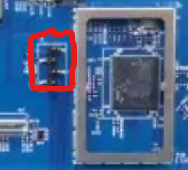
you need serial port access, which seems to be here, on the PCB:

What is needed to connect to the router using this? Do you have any suggestions for a specific one?
Something like https://www.amazon.com/dp/B00LODGRV8/
Sorry for the long wait, I final got a hold of the device that you recommended. When I went to use it, I found that nothing would come up when connecting to it. After some research I found that one pin, which I think is TX, would give 0 ohms when measured. I saw this line from OpenWRT's docs, "If you find something else, for example, that TX is shorted (0 Ohms) or that RX is open (OL = Open Line), this may mean that there is a resistor connecting a pin to GND that must be removed, or a resistor missing that is disconnecting the pin from the traces.", which led to more poking around, which led to me finding a resistor that directly leads into the shorted pin.
I'm wondering if any one has any advice on what I should do next? I assume that I should de solder the mentioned resistor. However, I don't have the money to buy a new R7960P or the skills to comfortably re-attach a new resistor if needed.
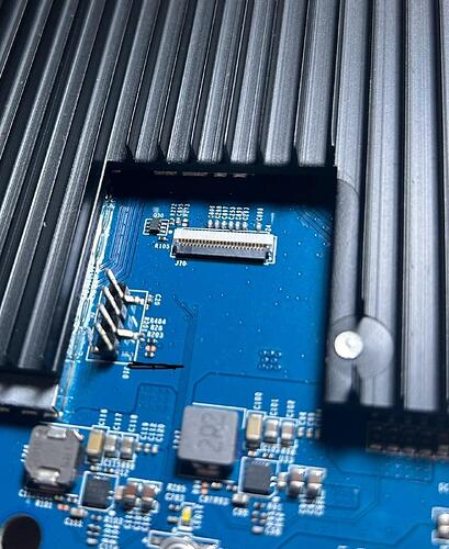
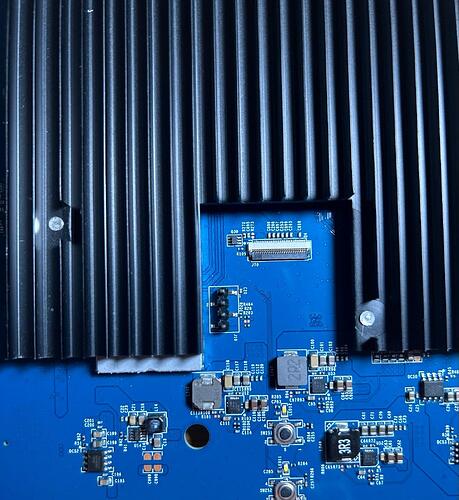
The picture below shows the serial port on the PCB and the resistor is above the black line, hopefully it sheds some light on what should be done:
Are there markings for Rx, Tx, etc on the PCB, next to the pins ?
Can't make it out from the photo.

