Need help adding support for the bt wifi disc

Hi i am currently trying to add support for the BT WIFI disc as an access point and i need some help as i don't have much experience at this.

The specs of the device are.

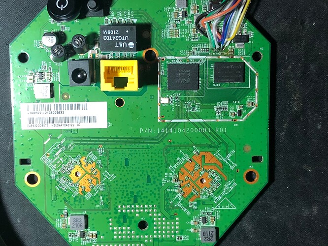
128MB of ram EtronTech EM6GC16EWXC-12BH
16MB of spi nor flash Winbond W25Q128JVSJQ
MT7621AT CPU
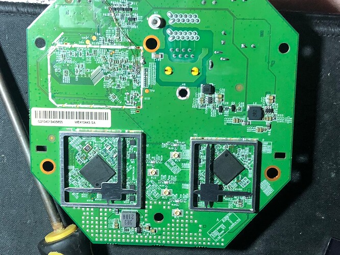
Dual MT7615N radio's
And a single gigabit ethernet port

It is pretty much identical to the D-Link DIR 882/878 A1 versions.

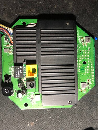
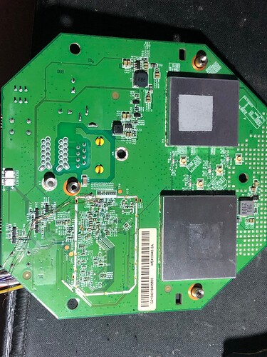
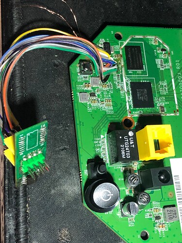
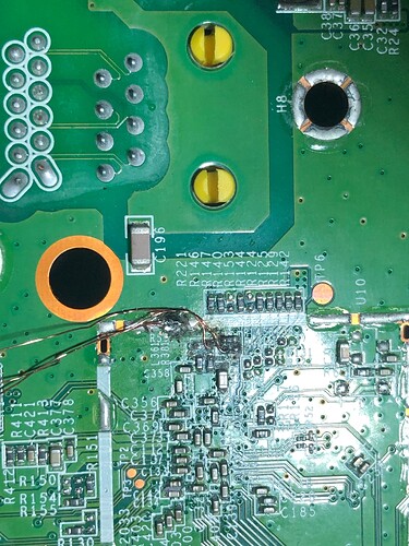
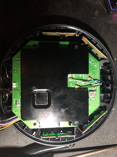
Here are some pics of the board.

Front.

Back.

Front without heatsink.

Back without heatsink.

Front without heatsink and rf shields.

Back picture of spi flash extension leads with connector so i can easily reprogram the chip.

Front picture of serial connection points.

I found these completely by luck i connected the rx pin of my usb to serial adapter to a multimeter probe and just touched traces and rebooted the disc until i found them.

This is the bt wifi disc default bootlog.

It seems the bt wifi disc is still sending stuff on serial after
SDK 5.0.S.0 as the light on my usb serial adapter blinks but nothing shows in putty.

I have tried changing the baud rate to a bunch of common ones and it still doesn't show anything readable.

I did get the dir 882 openwrt firmware fully working with wifi but i had to replace the uboot with the one for the dir 882 and copy over the config and factory partitions from the original bt wifi disc firmware to get it to work so here is the bootlog of that.

If i use the original uboot and upload the 882 a1 initramfs using tftp it gives me a bad header checksum error and here is the log of that.

So i zeroed out the 4 byte crc32 and recalculated it and reuploaded it using tftp and it got past that error and now it gives me a different error bad data crc and this is the log of that.

This is where im stuck and i have no idea how to fix this so any help would be appreciated.

Also i have all the gpio pins for all the leds and buttons as i had another bt wifi disc that was broken so i desoldered the cpu and traced out the pins
so when i get to making a custom image im just going to reuse the the dir 882 a1 image builder files and just modify the gpios to work with the bt wifi disc.

And I can provide full flash dumps of the default firmware if that helps.
Your post would be way easier to read and to understand if you used proper punctuation. I'm not sure if you phrased an actual question or just wanted to tell us that you are working on this device.

That said: The first step is usually to get access to the boot loader via a serial connection. Once this works, you can try to boot initramfs images via TFTP. In most cases, there is no need to desolder the flash IC.

I have edited my original post hopefully it is more clear.

ok i just got it working the openwrt image i was using was the dlink dir-882 a1 initramfs and i was getting the bad header checksum error and when i recalculated the header checksum it got past it but gave me the bad data checksum error.

So i was messing about and just tried the other dlink images the dir878 image failed same with the 867 but when i tried the dlink dir 882 r1 initramfs it just worked it fully booted.

looking at the techdata for the r1 version it seems that the flash layout is different from the a1 version and seems to match the bt wifi disc so i should be able to make a custom image from the r1 image builder files with the gpio edits for the bt wifi disc.

And once i have done that i will just need help adding it to the officially supported routers.

The DIR-882 has a non-standard header format, so it's probably not the best choice for a TFTP image: See the commit adding support for it, there is a uimage-padhdr command which probably confuses your bootloader.

When I add support for a new device, I usually start with a default configuration by adding the relevant entries for my device already to the Makefile and with a very basic DTS. That way, I can play around with the image generation steps.

In order to get the header right, I look at a dump from the device partition and/or a stock firmware upgrade file and try to understand the details.

As you've already found out by trial and error, the R1 doesn't have this uimage-padhdr call and that's the reason why it boots - here is the commit.

Thanks for the help though.

But quick question where would the gpio definitions be located in the dts file or some other file.

And once i have added a new board and made a working image how to i go about adding it to the officially supported routers.

Mostly in the dts. The only GPIO definition in modern targets outside the dts is a switch (an output, not an input like a button, that's in the dts).

Once you've got your changes ready, submit either a PR on github or send your patch to the mailing list. Regarding content and format have a look at recent commits and check the Wiki.