I have in my house 4 Access Points all running LEDE - there is a wired backbone between the rooms with the AP - that converge back to a single LEDE main router
I have a single Wifi Network for my trusted devices (shared SSID with different channels) and a Guest Wifi - Currently my guest wifi only runs from one router as I haven't worked out how to configure the switches on the APs to allow for Guest wifi on multiple Access points.
The routers are 3x TP-Link Archer C7s and a Linksys WRT3200ACM
Effectively what im trying to do is this:
How would this config look on the access points under the switch configuration (is it possible?)- I only want one wire between rooms/Access points
Assuming you've already got two VLANs chosen, one for trusted and one for guest. Pretend they're 3 and 4 for example with 3 your trusted LAN and 4 your guest network.
For each AP whatever port has the wired backbone connected to it, configure that port to belong to both 3 and 4 using tagged connection.
Configure the CPU port to belong to both vlans tagged as well. Then, Your physical layout for LAN and guest and wireless configs use eth0.3 and eth0.4 (or eth1 or whatever is appropriate for your hardware)
On the main router configure each of the ports that the APs are connected to to use VLAN 3 and 4 tagged, and make sure you have a guest interface on this router hooked up to the eth0.4 or whatever your guest vlan is. Make sure you have a separate firewall zone for guest.
voila!
For extra points, go back and check your configs again, the important thing being consistency of vlan tagging across all the backbones you don't want one AP feeding trusted packets to the router on the vlan for guest or vice versa.
Thank you both - i'm going to try it when I get home
I think I need to do a diagram of my network with devices on it to try and understand it more. Im looking at extending the Guest Wifi to the other APs, whilekeeping the guests off the trusted lan - that's the goal
Yep, this is definitely the way to achieve your goal. Basically a tagged VLAN means that each packet sent out of the port is tagged with an extra few bytes describing whether it belongs to guest or trusted, and also that tagged packets received on that port will be accepted rather than just dropped. It lets a single port participate in two or more streams of data while keeping those streams separate. one wire, multiple separate data streams.
It's not hard to configure, but monkeying with VLANs on your switch can cause you to lose connection to your routers or APs. One way to help avoid this is to connect on the trusted wlan rather than by wire. Backup your config first, and then worst-case if you do lock-out you use the failsafe mode: https://openwrt.org/docs/guide-user/troubleshooting/failsafe_and_factory_reset which I recommend you load up in a window on your computer before doing any of the monkeybusiness.
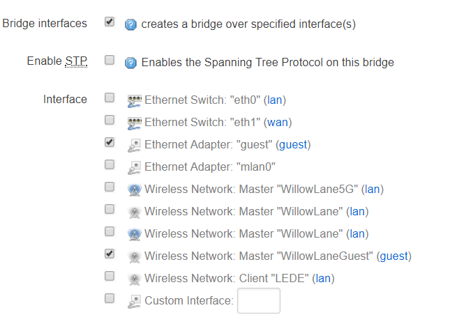
I tried but im a little confused. This is what my guest wifi interface setup looks like - It says its an Ethernet adapter - but isn't associated with the switch. How can I assigned a VLAN ID to an ethernet adaptor
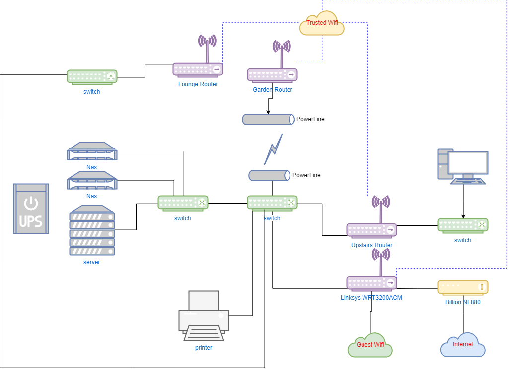
My network diagram
Currently the Guest Wifi is only setup on the Linksys
Would the first step be to configure it on one other of the APs
Right now you have only vlan 1 and 2 in your switch, and they're untagged. you'll want to configure a third one, vlan 3 for example and switch vlan 1 and 3 to tagged for one of the ports and for the cpu interface itself (eth0)
The ports thing I'm not sure what to put because I don't know your hardware but suppose that port 0 is eth0 and port 1 is your wired backhaul then you'd use that '0t 1t' stuff I put there. You have to verify which ports you're using, you can also do this config from LuCi "switch" config
Thanks @dlakelan really appreciate your time on this.
I think I get all that part, what I dont really understand is what is eth0 and eth1. They aren’t ports, I’m guessing they are just interfaces and don’t have much to do with the switch, until associated with the vlan tagging.
My router looks like this at the back and currently my WAN is on eth1 LAN on eth0
The VLAN notation can be eth0.1 and eth0.3 etc. Is the .3 or .1 the vlan ID?
On the guest network it allows me to set a custom interface. (Currently no way to set the guest part of the network on the vlan without it)
If the above is correct then I could set guest to eth0.3 then configure the vlan to have vlan 3 on the cpu for eth0 and the backhaul port, shared with vlan 1 on the same both being tagged and on both sides of the connection.
Is any of that correct? Trying to understand this before I start
Inside the router the CPU connects to the switch chip on a few board traces, these connections don't have an rj45 connector but they're still "ports" as far as the switch is concerned. The Luci switch page will help here, perhaps post a screenshot
As for eth0.3 yes the .3 refers to the vlan tag so all packets received on eth0 that are tagged w vlan 3 get shunted over to this virtual interface by the kernel.
What can I say - you guys inspired me to get this working - thank you
I only have a small part working - but I have a proof of concept and its working well.
I'm going to simplify whats working, from the bigger network.
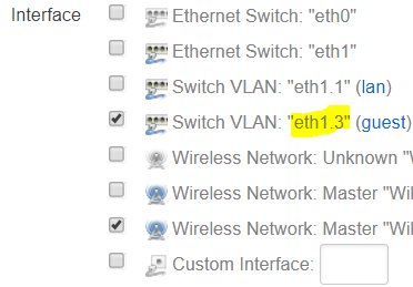
R2 Guest Interface
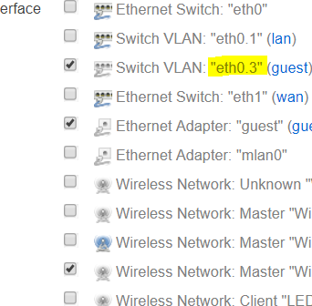
R1 Guest Interface
I have router 1 "R1" with (guest wifi setup channel 11, internet, DHCP), a managed switch "S1", and router 2 "R2" with (guest wifi setup channel 1)
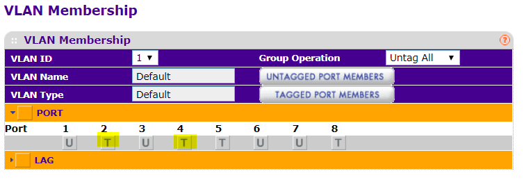
Port 1 on R1 connects to Port 2 of S1
Port 4 of S1 connects to Port 1 of R2
R1 runs eth0
R2 runs eth1
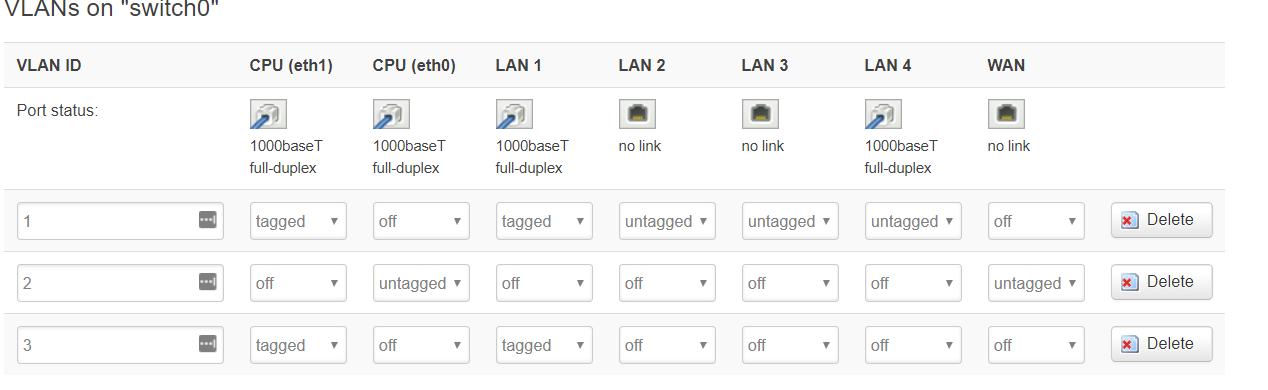
Two VLans configured 1 and 3. 1 for Trusted and 3 for Guest
On the guest interfaces I had to configure a custom iface either eth0.3 or eth1.3
Correct CPU tagged and interconnect wire port tagged - making sure my LAN connections were untagged