I'll open up the unit and probably have to solder in a header for serial access. As for GPL sources I am not sure about, I'll search around and see what I can find.
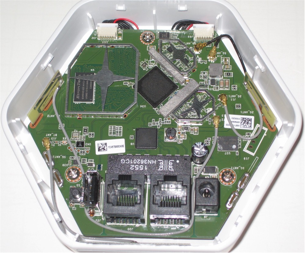
that thing on the right is definitely a serial header... sometimes oem just disable it in production by removing resistory before the serial header... Doesn't look in this case so... Serial should be plug-n-play ahhaha
J19 is indeed quite likely, especially as it was populated with a header (which fooled me into thinking that it was part of the connection to the light board) in the FCC pictures.
I thought so as well 
Now time to open one up, will be a little while as I am away for a bit.
Thought this info might be of use. Luma is running a customized version of OpenWRT
Browsed to IP: 192.168.55.1, got the below info
deos v2018.01.22-0
process
| dconf::uptime | 1d 0h 31m 26s |
|---|---|
| libc::allocated | 1346720b (1.28mb) |
| cc::version | 4.8.3 |
| cc::builddate | Jan 23 2018 09:29:10 |
| fw::buildver | jenkins-luma-firmware-office-build-server-872 |
| libc::version | µClibc 0.9.33 |
| ssl::version | OpenSSL 1.0.2f 28 Jan 2016 |
environment
| uname::machine | armv7l |
|---|---|
| uname::sys | Linux 3.14.43 #1 SMP PREEMPT Fri Feb 24 17:17:23 EST 2017 |
| sys::uptime | 1d 0h 32m 36s |
| sys::processes | 140 |
| sys::load1m | 0.16 |
| sys::load15m | 0.25 |
| sys::totalram | 241mb |
| sys::freeram | 56mb |
| net::w0_channel | 1 |
| net::w1_channel | 149 |
Port scan revealed the following:
luma.lan
| Status: | Alive |
|---|---|
| Operating system: | Linux |
| IP: | 192.168.55.1 |
| MAC: | |
| Manufacturer: | |
| NetBIOS: | |
| User: | |
| Type: | Wireless access point |
| Date: | |
| Comments: |
| Service | Details |
|---|---|
| HTTP | |
| Port 53 (TCP) | domain |
| Port 80 (TCP) | |
| Port 4369 (TCP) | Erlang Port Mapper Daemon |
| Port 5000 (TCP) | MiniUPnP 1.8 OpenWrt Barrier Breaker r48529; UPnP 1.1 |
| Port 5001 (TCP) |
Seems that a few devices with the same CPU and SWITCH combo have been ported to OpenWRT. Still waiting to get back home so I can hook up my TTL cable
https://openwrt.org/toh/views/toh_extended_all?dataflt[CPU*~]=IPQ4018&dataflt[Switch*~]=QCA8075
Anything going on here? I would like to help. I need to be able to set the wan address on the luma and this is probably going to be the only way for me to do that.
Haven't had a chance to go any further with this for now. Got the JTAG pins soldered in and connected to the terminal, but it won't accept any keyboard inputs. Will try again later, just busy with work.
Has any of this research lead to ideas (beyond factory reset) for how to recover a bricked / swirling blue Luma that doesn't respond to resets?
How the heck did you get it open?
The plastic clips holding it together are very visible in the pictures above.
I asked "how" not "what" but thanks anyway.
So, I opened it up by tracing the little gap at the bottom around the first corner going clockwise with a putty knife, sliding inside most of the way, then leveraging the top open by pulling away. Took a lot of force, so be careful!
Yes, that J19 is a serial header, at 115200 baud. The pin nearest the power connector is GND, and the next two are RX/TX.
Here's the boot log:
You can get to a root terminal by getting into "failsafe mode" by typing "f" then enter during bootup!
I'm not sure what to do next... (time to read some openwrt page about porting to a new device!).
1 Like
After getting to failsafe, invoke mount_root, it mounts ubi rootfs. Next type fw_printenv and store values somewhere safe. Next sed -e 's/root:x:/root::/' -i /etc/passwd to reset asking for password and also fw_setenv bootdelay 3 to have possibility to acces U-Boot shell. After rebooting login as root, now You can play fo example with led ring with led_ctl command, enjoy.
I have been poking this device since Friday, basic things work already on OpenWrt. What's missing is:
- finding gpios activating i2c,
- ready to flash image,
- a way to disable leds ring.
1 Like
That works!
So what target are you using for an openwrt build for this? And how would we flash the resulting image to the device now?
No image for flashing is ready yet. The nand flash seems to be storing two sets of kernel and rootfs, one of the set seems to be a backup, but I can't trigger the backup set. Don't know if that was ever implemented and that is main decision which will affect creation of image to flash. Keep the flash layout and replace one set of kernel+rootfs or mark the whole flash for OpenWrt to use it.
The target in use is ipq40xx. You can use this image to boot the board from U-Boot using TFTP server: https://downloads.openwrt.org/snapshots/targets/ipq40xx/generic/openwrt-ipq40xx-generic-qcom_ap-dk01.1-c1-initramfs-fit-uImage.itb
This image will leave no permanent changes.
Remember DO NOT flash any image yet. There's no OEM image for download in case You want to revert to factory.
1 Like
Wow. That works!
For reference, what I did was:
hit a key during boot to get to uboot menu
type "help" to see commands
type "tftpboot"
read what was there and then setup my computer/tftpserver to be on the right ip address and the file in the right place with the right name:
sudo cp openwrt-ipq40xx-generic-qcom_ap-dk01.1-c1-initramfs-fit-uImage.itb /srv/tftp/C0A80B0E.img
type "bootm"
I see this in dmesg...
[ 43.990259] i2c-gpio i2c-gpio.0: using pins 1 (SDA) and 0 (SCL)
There does seem to be i2c traffic (verified with a scope) on two of the black wires leading to the led board. The other wires are all at GND, 3.3V, or 5V.
Actually, the SDA and SCL go to Test Points (TP3 and TP4) near the microprocessor on the LED board, respectively. I soldered wires to them, and fed them into A4 and A5 on an arduino, and ran this slave i2c code to spy on the data as I sent led_ctl commands from the luma: https://www.arduino.cc/en/Tutorial/MasterWriter
I could tell that the luma was addressing 0x48 by doing:
i2cdetect -y 0 (on the luma)
There also seems to be some devices at 0x50-0x57, but only 0x57 has any data, which you can see with e.g.:
i2cdump -y 0 0x57
It seems to be the default wifi ssid of the device, something I can't recognize, and the serial number. It's likely a flash nvram.
You can read/write from/to it with e.g.:
i2cset -y 0 0x56 0x40 0xef
i2cget -y 0 0x56 0x40
But I digress!
The LEDs can be controlled with i2cset commands just like they can from led_ctl. See the led_ctl commands below. Each command has up to four numbers. The first is the mode, the second is the color, and the third and forth depends on the command. For instance,
i2cset -y 0 0x48 3 1 9 0 i
would set it to solid red brightness=9 (and the fourth value is not used for that command).
The modes go from 3 to 8, for solid to pulsing.
The colors go from 1 to 7, for red to white (except blue and yellow are switched, so it really goes red, green, yellow, blue, purple, cyan, white).
root@luma:~# led_ctl
Usage: led_ctl [status | upgrade | force_upgrade | version]
led_ctl solid COLOR
led_ctl single COLOR INDEX <brightness 0 - 15>
led_ctl spinning COLOR <period 1 - 16 (lower = faster)>
led_ctl fill COLOR <period 1 - 16 (lower = faster)>
( default is 5 )
led_ctl flashing COLOR <on dur 1 - 128> <off dur 1 - 128>
(default is 34) ( default is 34 )
led_ctl pulsing COLOR
COLOR: red, green, blue, yellow, purple, cyan, white