Ok, so I have a couple of these little extenders, and I want to see if I can port OpenWRT to it. Here is my documentation so far:
Disassembly
See Photos Here: https://photos.app.goo.gl/Pq5FZme7brABStMk6
- There is a single screw hiding under the label at the bottom edge. Be wary when disassembling.
- There are clips all around the edge. There are two on each edge, so 8 in total (2 clips x4 edges)
- Once apart, there are 4 screws, 2 at the bottom, 1 at the top middle, and one on the left side.
- The part underneath I think is just a power supply. The main board is the top part.
- The main board has two plastic pins holding the heat spreader on. Remove carefully, a set of small needle-nosed pliers should help. It may stick a bit, just pull gently with your fingers.
Info
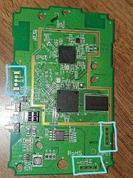
The main board (In High Def!)
Main componenets:
- MT7628AN - https://openwrt.org/docs/techref/hardware/soc/soc.mediatek
- MT7612EN - https://www.mediatek.com/products/broadbandWifi/mt7612e
- W9751G6KB-25 - https://www.mouser.com/ProductDetail/Winbond/W9751G6KB-25?qs=qSfuJ%2Bfl%2Fd5rDwtO4A14Hw%3D%3D
The Main CPU is fully supported already by OpenWRT, and the second chip is a coprocessor usually included when the main CPU is used in a router/extender. My guess is it is to add a second WiFi "card" to the chip, so it can act as an extender. The main chip appears to be able to act on its own if you only needed one radio.
The third one is just a 512Mb DDR2 RAM module.
If you look at the highlighted pieces, there appears to be a mystery switch (with no switch attached) and two junction headers, J1 and J10.
I'm guessing J1 is a Serial Header, J10 might be a USB or an extra Serial header.
Also, I traced the antenna lines, and one runs to the main processor, and the other runs to the co-processor, possibly confirming my theory of the second chip acting as a separate WiFi "card" so the extender can operate properly.
Conclusion
I'm pretty sure this board could almost run OpenWRT right away, except for a few pin assignments and port adjustments. I just need some help on that front. If anyone is willing to help me out, just post here and I'm sure we can figure this device out and add it to the growing list of compatible devices.
P.S.: If any of you guys want or need High-Res pics of the board for tracing purposes, let me know. I can borrow a T3i and get the pics taken.
Also, On Saturday Im gonna see if I can use my USB Serial dongle to connect to this device and see what it's running. Hope I can figure it out!
