I've just installed LEDE 17.01.0 on a Technicolor TG582n DANT-T I gathered most information from the OpenWRT wiki page, and followed the procedure shown there, with few changes that I'll share here in the coming days--I have so little time
As I said, I have a DANT-T board (there are two different other versions of TG582n, namely DANT-1 and DANT-V, the main difference being the flash chip). The OpenWRT wiki page says that the flash installed on DANT-T boards is MX25L6445EMI, however in my case it is a Winbond 25Q64FVFIG [1]:
Another thing I noticed in the LEDE project page [1] is that the suggested image is lede 17.01.0 A4001N1, which is good for DANT-1. However for DANT-T you need the A4001N image [2]. I still need to check whether I can edit the LEDE project page and correct this.
Yes @tmomas, you're perfectly right, we don't know what image version we need for DANT-V. I can't find that information in the openwrt page. Unfortunately, in an attempt to post some pictures, I managed to be banned from the openwrt forum, so I can't ask there either.
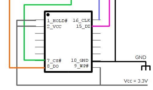
The first thing to do is loading a CFE bootloader image [1] on the flash ROM. The stock bootloader does not allow to install the LEDE firmware on it. To flash the ROM with the CFE image, we need some electrical wiring.
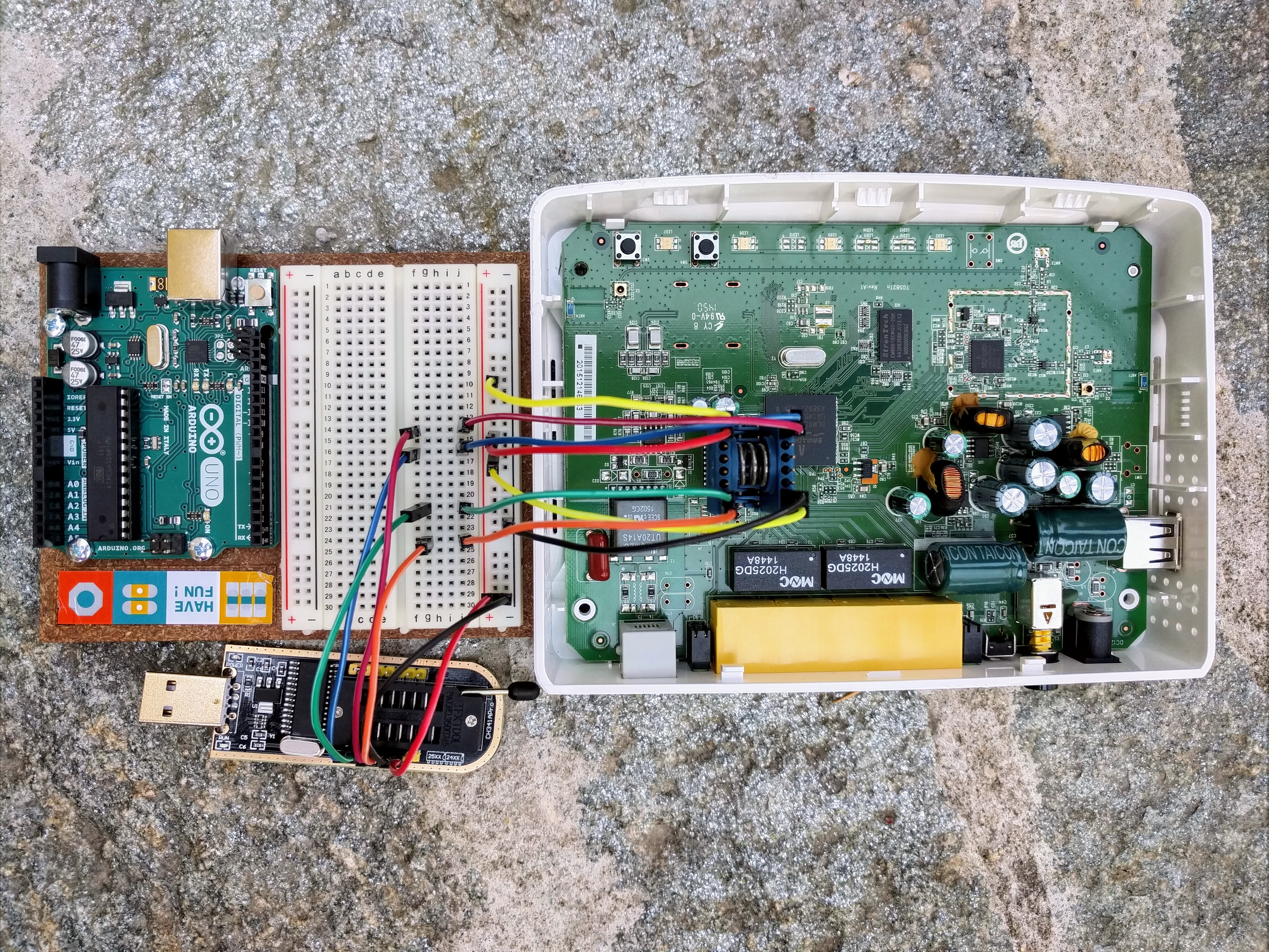
Instead of soldering wires to the flash chip (as explained in the OpenWRT wiki page), I used a 16 pin SOIC test clip, the Pomona 5252 [2].
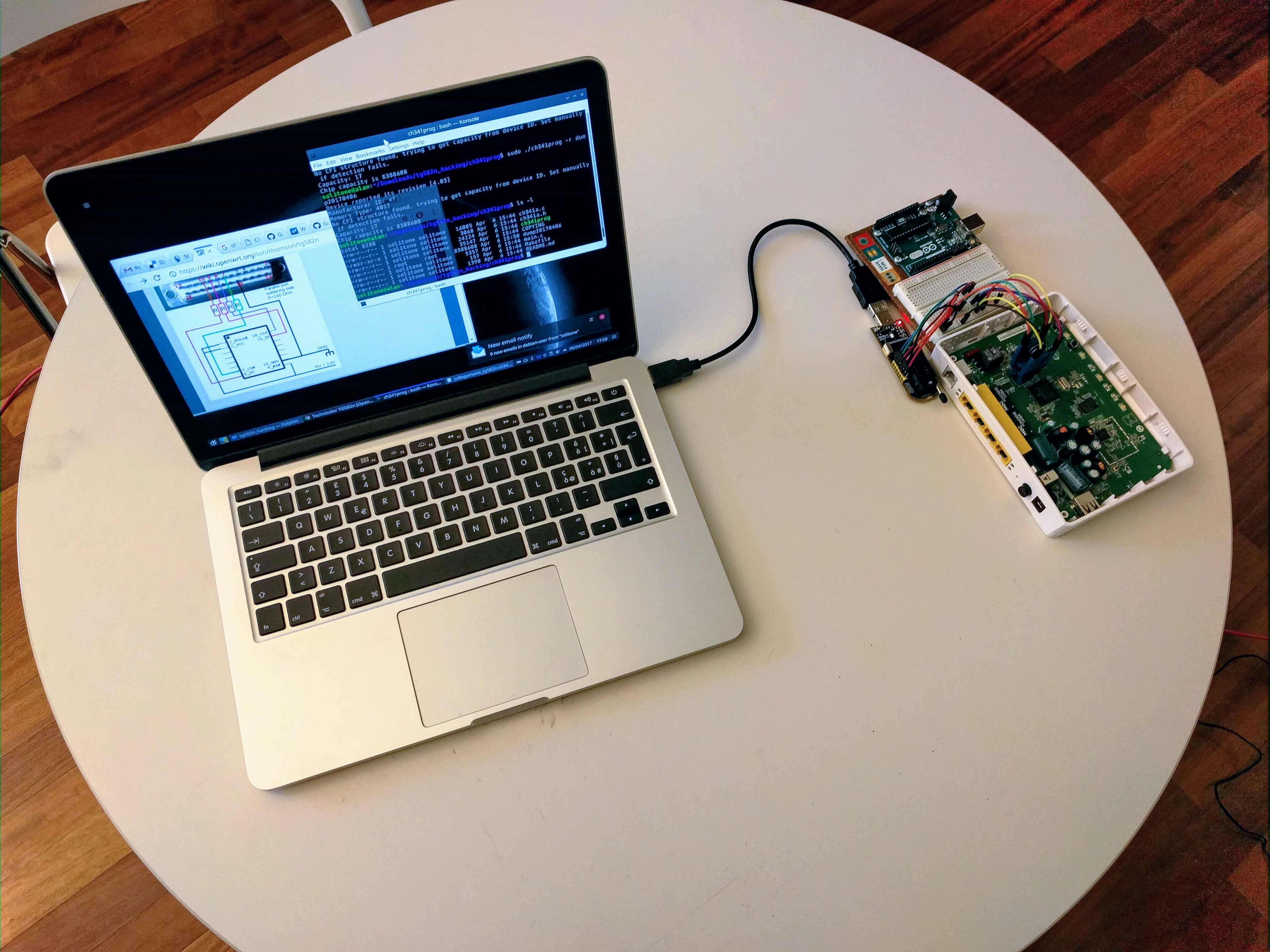
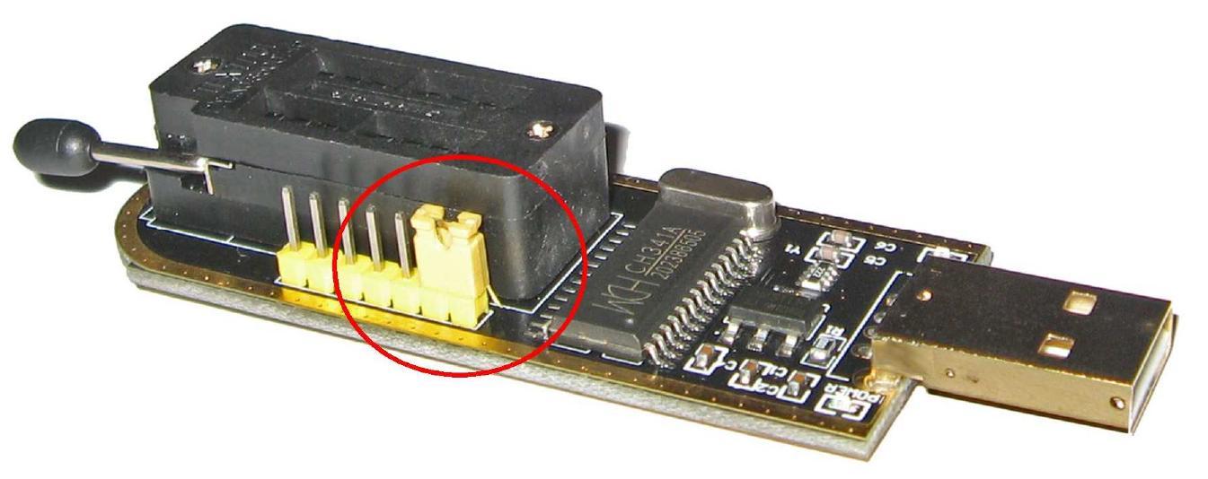
I don't have a parallel port on my PC, so I didn't built an interface with a parallel port cable, but simply bought on ebay an SPI programmer based on the ch341a chip [3], which I connected to a USB port on my PC. The connection between the programmer and the test clip was realized with some jumper cables and a breadboard.
The software tools provided with the ch341a device work only under Windows. Since I am under linux, I had to find something different, and ch341prog is what I needed. It compiled with no fuss on debian GNU/linux 9 (stretch).
I did a: $ sudo ./ch341prog -i
to confirm that I indeed have 8MB flash ROM. With: $ sudo ./ch341prog -r stock_rom_dump.bin
I backed up what I had in the flash, and finally with a: $ sudo ./ch341prog -w cfe6328_configured.bin
I flashed the CFE bootlader.
I haven't got a Windows machine, so I can't test the procedure on Windows, but with the provided drivers and documentation there should be no issue either.
After flashing the new bootloader, you can reconnect the normal power supply, connect the TG882n to your computer with an ethernet cable and power the box on. I flashed the already configured CFE image (cfe*_configured.bin), so after rebooting the box I had the bootloader listening on 192.168.2.50, as explained in the OpenWRT wiki page. From there it was quick and easy to installa the LEDE 17.01.0 A4001N image [1].
I hope this quick guide can help others. If you have questions please let me know.
@tmomas, now I understand what you mean. I'm trying and editing that page (the right way, i.e. with the lower left edit button), and I am presented with only one field for firmware LEDE install URL, so I can't split the current entry. What would be the best approach for editing so?
Thank you for doing this. It's perfect and so simple.
I've never done anything like this before, but, I ordered the Pomona and SPI programmer yesterday, within an hour of it arriving along with a bread board and set of wires I'd managed to get LEDE loaded and running.
I've done everything and I've installed the O.S LEDE on my technicolor TG582n. The tutorial was perfect.
I want ask only two things:
Is the wifi working? Because i tried a lot of things, like update all the packages... But nothing. There isn't the file /etc/config/wireless and i don't know if i'll make it.
 I gathered most information from the OpenWRT wiki page, and followed the procedure shown there, with few changes that I'll share here in the coming days--I have so little time