First of all I would like to say hello to everyone ![]()
this is a new [how to] but please take a look at my other how-tos from the old Openwrt forum:
[https://forum.archive.openwrt.org/viewtopic.php?id=49013&p=1](http://pilovis OpenWRT How TOs)
and also the new ones:
[How To] Add barometric pressure and temperature sensor to Openwrt
[How to] connect a DHT12 I2c humidity and temperature sensor to OpenWrt and display values on LCD
https://forum.openwrt.org/t/how-to-install-rtc-hardware-clock-pcf8563-i2c/43566
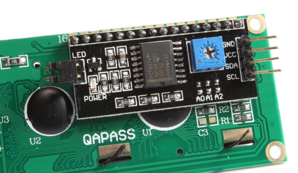
Router I used: TP-Link TL-WDR 4300 + LCD 20x4 lines mod HD44780 with I2C interface:

OpenWrt 18.06.1
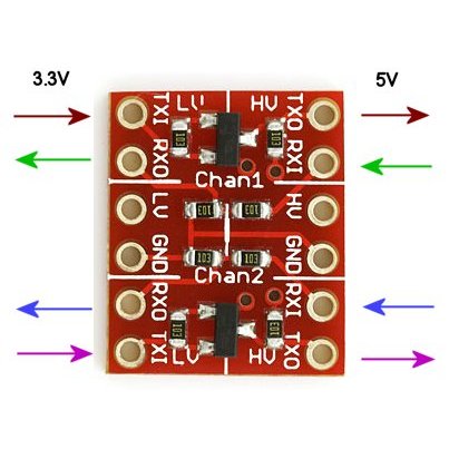
prerequisites
Important note: there is not enough space on this router (Flash=8MB), USB external overlay is needed!
opkg update
opkg install kmod-i2c-gpio kmod-i2c-gpio-custom kmod-i2c-core kmod-i2c-algo-bit
opkg install i2c-tools
opkg install kmod-i2c-smbus
opkg install python
opkg install python-dev
opkg install python-smbus
opkg install git git-http
I2C configuration
Note: I'm using GPIO 2 & 3 of TP-Link TL-WDR 4300 for I2C
gpio-2 (SDA) = JP1-5
gpio-3 (SCL) = JP1-7
set pins for I2C:
/sbin/rmmod leds-gpio
/sbin/insmod i2c-dev
/sbin/insmod i2c-gpio-custom bus0=0,2,3
note: add the above lines to /etc/rc.local to set I2C pins at startup
check I2C:
/bin/dmesg |grep i2c
if everything is OK you shoud see the following:
root@OpenWrt:~# /bin/dmesg |grep i2c
[   34.835378] i2c /dev entries driver
[   78.331772] i2c-gpio i2c-gpio.0: using pins 2 (SDA) and 3 (SCL)
Now, we can search for I2C devices, connected to the bus:
i2cdetect 0
note: I have an i2c device accessible on address 0x27 on the bus number 0.
If you have a different numbers adapt them to the following "I2C_LCD_driver.py" script by changing the line: "ADDRESS = 0x27".
software (python scripts)
nano /etc/I2C_LCD_driver.py
# -*- coding: utf-8 -*-
# Original code found at:
# https://gist.github.com/DenisFromHR/cc863375a6e19dce359d

"""
Compiled, mashed and generally mutilated 2014-2015 by Denis Pleic
Made available under GNU GENERAL PUBLIC LICENSE

# Modified Python I2C library for Raspberry Pi
# as found on http://www.recantha.co.uk/blog/?p=4849
# Joined existing 'i2c_lib.py' and 'lcddriver.py' into a single library
# added bits and pieces from various sources
# By DenisFromHR (Denis Pleic)
# 2015-02-10, ver 0.1

"""

# i2c bus (0 -- original Pi, 1 -- Rev 2 Pi)
I2CBUS = 0

# LCD Address
ADDRESS = 0x27

import smbus
from time import sleep

class i2c_device:
   def __init__(self, addr, port=I2CBUS):
      self.addr = addr
      self.bus = smbus.SMBus(port)

# Write a single command
   def write_cmd(self, cmd):
      self.bus.write_byte(self.addr, cmd)
      sleep(0.0001)

# Write a command and argument
   def write_cmd_arg(self, cmd, data):
      self.bus.write_byte_data(self.addr, cmd, data)
      sleep(0.0001)

# Write a block of data
   def write_block_data(self, cmd, data):
      self.bus.write_block_data(self.addr, cmd, data)
      sleep(0.0001)

# Read a single byte
   def read(self):
      return self.bus.read_byte(self.addr)

# Read
   def read_data(self, cmd):
      return self.bus.read_byte_data(self.addr, cmd)

# Read a block of data
   def read_block_data(self, cmd):
      return self.bus.read_block_data(self.addr, cmd)


# commands
LCD_CLEARDISPLAY = 0x01
LCD_RETURNHOME = 0x02
LCD_ENTRYMODESET = 0x04
LCD_DISPLAYCONTROL = 0x08
LCD_CURSORSHIFT = 0x10
LCD_FUNCTIONSET = 0x20
LCD_SETCGRAMADDR = 0x40
LCD_SETDDRAMADDR = 0x80

# flags for display entry mode
LCD_ENTRYRIGHT = 0x00
LCD_ENTRYLEFT = 0x02
LCD_ENTRYSHIFTINCREMENT = 0x01
LCD_ENTRYSHIFTDECREMENT = 0x00

# flags for display on/off control
LCD_DISPLAYON = 0x04
LCD_DISPLAYOFF = 0x00
LCD_CURSORON = 0x02
LCD_CURSOROFF = 0x00
LCD_BLINKON = 0x01
LCD_BLINKOFF = 0x00

# flags for display/cursor shift
LCD_DISPLAYMOVE = 0x08
LCD_CURSORMOVE = 0x00
LCD_MOVERIGHT = 0x04
LCD_MOVELEFT = 0x00

# flags for function set
LCD_8BITMODE = 0x10
LCD_4BITMODE = 0x00
LCD_2LINE = 0x08
LCD_1LINE = 0x00
LCD_5x10DOTS = 0x04
LCD_5x8DOTS = 0x00

# flags for backlight control
LCD_BACKLIGHT = 0x08
LCD_NOBACKLIGHT = 0x00

En = 0b00000100 # Enable bit
Rw = 0b00000010 # Read/Write bit
Rs = 0b00000001 # Register select bit

class lcd:
   #initializes objects and lcd
   def __init__(self):
      self.lcd_device = i2c_device(ADDRESS)

      self.lcd_write(0x03)
      self.lcd_write(0x03)
      self.lcd_write(0x03)
      self.lcd_write(0x02)

      self.lcd_write(LCD_FUNCTIONSET | LCD_2LINE | LCD_5x8DOTS | LCD_4BITMODE)
      self.lcd_write(LCD_DISPLAYCONTROL | LCD_DISPLAYON)
      self.lcd_write(LCD_CLEARDISPLAY)
      self.lcd_write(LCD_ENTRYMODESET | LCD_ENTRYLEFT)
      sleep(0.2)


   # clocks EN to latch command
   def lcd_strobe(self, data):
      self.lcd_device.write_cmd(data | En | LCD_BACKLIGHT)
      sleep(.0005)
      self.lcd_device.write_cmd(((data & ~En) | LCD_BACKLIGHT))
      sleep(.0001)

   def lcd_write_four_bits(self, data):
      self.lcd_device.write_cmd(data | LCD_BACKLIGHT)
      self.lcd_strobe(data)

   # write a command to lcd
   def lcd_write(self, cmd, mode=0):
      self.lcd_write_four_bits(mode | (cmd & 0xF0))
      self.lcd_write_four_bits(mode | ((cmd << 4) & 0xF0))

   # write a character to lcd (or character rom) 0x09: backlight | RS=DR<
   # works!
   def lcd_write_char(self, charvalue, mode=1):
      self.lcd_write_four_bits(mode | (charvalue & 0xF0))
      self.lcd_write_four_bits(mode | ((charvalue << 4) & 0xF0))

   # put string function with optional char positioning
   def lcd_display_string(self, string, line=1, pos=0):
    if line == 1:
      pos_new = pos
    elif line == 2:
      pos_new = 0x40 + pos
    elif line == 3:
      pos_new = 0x14 + pos
    elif line == 4:
      pos_new = 0x54 + pos

    self.lcd_write(0x80 + pos_new)

    for char in string:
      self.lcd_write(ord(char), Rs)

   # clear lcd and set to home
   def lcd_clear(self):
      self.lcd_write(LCD_CLEARDISPLAY)
      self.lcd_write(LCD_RETURNHOME)

   # define backlight on/off (lcd.backlight(1); off= lcd.backlight(0)
   def backlight(self, state): # for state, 1 = on, 0 = off
      if state == 1:
         self.lcd_device.write_cmd(LCD_BACKLIGHT)
      elif state == 0:
         self.lcd_device.write_cmd(LCD_NOBACKLIGHT)

   # add custom characters (0 - 7)
   def lcd_load_custom_chars(self, fontdata):
      self.lcd_write(0x40);
      for char in fontdata:
         for line in char:
            self.lcd_write_char(line)
nano /etc/test.py
# OpenWrt I2C LCD 20x4 display
# by Lovisolo P.M. - parknat12@yahoo.com
# my OpenWRT, Raspberry and Linux, personal forum: http://forum.49v.com
import I2C_LCD_driver
import time
import sys
import commands
from subprocess import check_output
from shlex import split
mylcd = I2C_LCD_driver.lcd()

mylcd.lcd_display_string("OpenWrt I2c to LCD ", 1)
mylcd.lcd_display_string("by Lovisolo PM 2019", 2)
mylcd.lcd_display_string("-------------------", 3)
mylcd.lcd_display_string("parknat12@yahoo.com", 4)
time.sleep(10)

mylcd.lcd_clear()

while True:
	mylcd.lcd_display_string(sys.argv[1], 1)
	mylcd.lcd_display_string(sys.argv[2], 2)
	mylcd.lcd_display_string(sys.argv[3], 3)
	mylcd.lcd_display_string("%s" %time.strftime("%H:%M:%S" " " "%d/%m/%Y"), 4)
	# little sleeping will reduce cpu usage
	time.sleep(0.2)
nano /root/start-lcd.sh
#!/bin/bash
#while :
#do
wan=`/sbin/ifconfig wlan0 | grep 'inet addr:' | cut -d: -f2 | awk '{ print $1}' | sed 's/ //g'`
lan=`/sbin/ifconfig br-lan | grep 'inet addr:' | cut -d: -f2 | awk '{ print $1}' | sed 's/ //g'`
#internet=`wget http://ipecho.net/plain -O - -q`
#signal=`iw dev wlan0 station dump | grep 'signal:' | cut -d '[' -f 1 | cut -d ':' -f 2 | sed 's/ //g'`
station=`iwconfig wlan0 | grep 'ESSID:' | cut -d ':' -f 2 | sed 's/ //g' | sed 's/\"//g'`
/usr/bin/python /etc/test.py "SSID:$station" "wan:$wan" "lan:$lan"
# done
give the right permissions to the above script:
chmod 755 /root/start-lcd.sh
Start LCD showing
/bin/sh /root/start-lcd.sh
this script will show the following:
SSID:
WAN IP
LAN IP
Time and date (live)