Hi all,
The UFI001 4G modem offer 512Mb ram, 4G of flash, plus Wifi and 4G modem for a price under 10$ where I live. This is a steal, consider some folks already managed to run Handsomemod or ImmortalWRT on it.


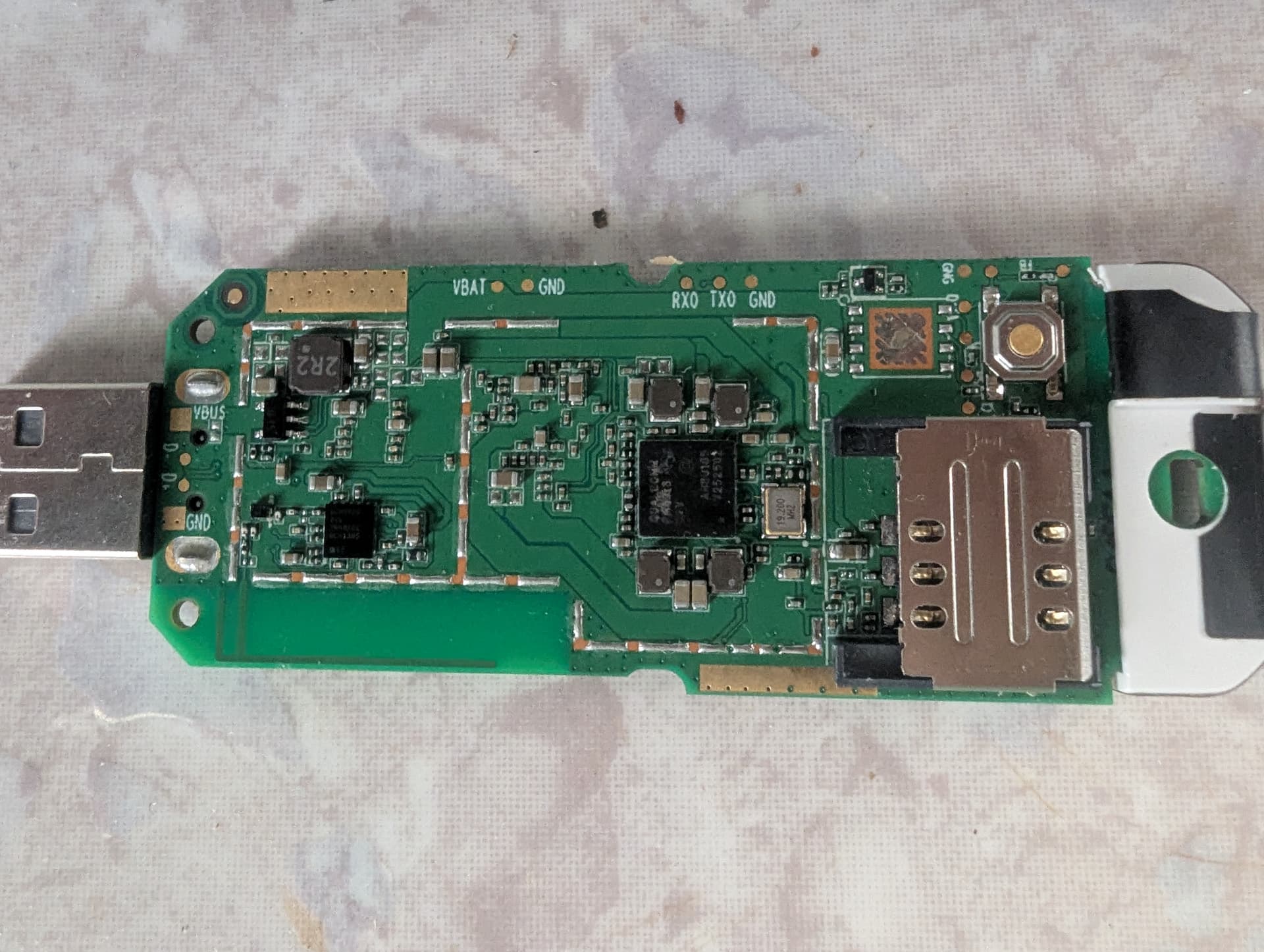
Unfortunately, it came in many board revision, and I landed on a (presumably) new board revision of HMUF02-V05 that have not received support yet. After a long search, there is no dts for this particular board on the Internet. I have hoped that the GPIO pin mapping matches some other board like UFI001b, UF896,.. but it turned out that the pin mapping is different. Thus there is no way that modem could work!
Upon compile HandsomeMod for UFI001b and install, I am able to boot into the OS. However, as I have expected, the modem did not turned on, showing "sim-missing" even after I placed the stock modem firmware file into /lib/firmware.
  -----------------------------------
  General  |                    path: /org/freedesktop/ModemManager1/Modem/0
           |               device id: d80ae90353f7573e48136b26ab94f34108de78c0
  -----------------------------------
  Hardware |            manufacturer: 1
           |                   model: 0
           |       firmware revision: HIMI_U01_MODEM_V2.0  1  [May 13 2022 13:00:00]
           |          carrier config: ROW_Generic_3GPP
           | carrier config revision: 02010801
           |            h/w revision: 10000
           |               supported: gsm-umts, lte
           |                 current: gsm-umts, lte
           |            equipment id: [redacted]
  -----------------------------------
  System   |                  device: qcom-soc
           |                 drivers: rpmsg_chrdev, bam-dmux
           |                  plugin: qcom-soc
           |            primary port: rpmsg0
           |                   ports: rpmsg0 (qmi), rpmsg1 (at), rpmsg_ctrl2 (ignored),
           |                          wwan0 (net), wwan1 (net), wwan2 (net), wwan3 (net), wwan4 (net),
           |                          wwan5 (net), wwan6 (net), wwan7 (net)
  -----------------------------------
  Status   |                   state: failed
           |           failed reason: sim-missing
           |          signal quality: 0% (cached)
  -----------------------------------
  Modes    |               supported: allowed: 3g; preferred: none
           |                          allowed: 4g; preferred: none
           |                          allowed: 3g, 4g; preferred: 4g
           |                          allowed: 3g, 4g; preferred: 3g
           |                 current: allowed: any; preferred: none
  -----------------------------------
  Bands    |               supported: utran-1, utran-5, utran-8, eutran-1, eutran-3, eutran-5,
           |                          eutran-8
  -----------------------------------
  IP       |               supported: ipv4, ipv6, ipv4v6
I proceed to unpack the stock boot image and extract the dtb from it. Then I decompiled the dtb into dts using dtc. Got the following interesting lines (see attached dts file for full dump):
gpio_leds {
			compatible = "gpio-leds";
			status = "okay";
			pinctrl-names = "default";
			pinctrl-0 = <0xe0>;

			ftest {
				gpios = <0x2f 0x6a 0x00>;
				label = "ftest";
				linux,default-trigger = "none";
				default-state = "keep";
				retain-state-suspended;
			};

			wifistatus {
				gpios = <0x2f 0x49 0x00>;
				label = "wifistatus";
				linux,default-trigger = "none";
				default-state = "off";
				retain-state-suspended;
			};

			4g_1 {
				gpios = <0x2f 0x47 0x00>;
				label = "4g_1";
				linux,default-trigger = "none";
				default-state = "off";
				retain-state-suspended;
			};

			4g_type {
				gpios = <0x2f 0x48 0x00>;
				label = "4g_type";
				linux,default-trigger = "none";
				default-state = "off";
				retain-state-suspended;
			};

			esim1_en {
				gpios = <0x2f 0x77 0x00>;
				label = "esim1_en";
				linux,default-trigger = "none";
				default-state = "keep";
				retain-state-suspended;
			};

			esim2_en {
				gpios = <0x2f 0x0e 0x00>;
				label = "esim2_en";
				linux,default-trigger = "none";
				default-state = "keep";
				retain-state-suspended;
			};

			esim3_en {
				gpios = <0x2f 0x0c 0x00>;
				label = "esim3_en";
				linux,default-trigger = "none";
				default-state = "keep";
				retain-state-suspended;
			};

			sim_hotplug {
				gpios = <0x2f 0x72 0x00>;
				label = "sim_hotplug";
				linux,default-trigger = "none";
				default-state = "keep";
				retain-state-suspended;
			};

			bat1 {
				gpios = <0x2f 0x24 0x00>;
				label = "bat1";
				linux,default-trigger = "none";
				default-state = "off";
				retain-state-suspended;
			};
I was able to confirm that this seems to be the correct dts for this board as I found the red, green and blue leds gpios by using an exhaustive search script. It read and store the original GPIO pins state, then turned on each GPIO pin for 1s, then reset the state. However, the file contain only esim_enable gpios, without sim_select gpios as on the UFI001b. A close inspection of the board reveal that it contains 3 "sim": 1 physical, 2 esim but unsoldered. But apart from that, I do not have any other information to continue.
I guess that the gpio for selecting the physical sim is always on since the esim is missing? However, modem did not work when I manually turned on gpio509 (gpiochip offset 390). It should have worked if that hypothesis is correct.
Can anyone offer any advice?