Do you mean this one? https://doc.lagout.org/electronics/doc/lexra/lx4189-datasheet-1.9-c20081030.pdf
Yeah, I've read it before. It shows some of the bus signals, which is what the DMA units would ultimately use, and mentions the burst side of things. But doesn't provide any actual register info on the DMA units. So I'm just going off the reasonably comprehensive test code.
There's obviously still a few tweaks that I'm missing however... I've had it work a couple of times when I'm just walking through transactions in uboot (at the 0xB8... aliased ranges)... but it appears to have stopped working for me... which is a little concerning. The DMA units say that they've completed, and set the Interrupt flags for it. But the memory addresses I thought I was having it write to show up with their original values...
I've probably made some simple mistake somewhere.
DMA wise, I think I can have it handle both Option A and Option B in the same driver. I've already got it looping through each reg entry and creating a channel against that DMA device for it. So if each DMA device only has a single reg entry, then each DMA device only has a single physical channel associated with it. If one DMA device has three reg entries, then it gets three physical channels.
My annoyance there however is that in Linux DMA driver / DT world... once you associate one device with a DMA channel, that channel is no longer available for any other device.
Here's an example with a single channel, when the dmatest module is assigned to it.. (and trying to spin up multiple threads with multiple channels)
This is also where my current implementation sits..
[  388.824495] dmatest: dma0chan0-copy0: result #98: 'test timed out' with src_off=0x179 dst_off=0xaf len=0x3dec (0)
[  388.824495] dmatest: dma0chan0-xor0: result #98: 'test timed out' with src_off=0x1246 dst_off=0x1a5a len=0xe3d (0)
[  388.825864] rtl_gdma 1800a000.dma: Entered rtk_gdma_prep_dma_memcpy, max_segment_length=8191
[  388.838775] rtl_gdma 1800a000.dma: Entered rtk_gdma_prep_dma_xor, max_segment_length=8191
[  388.847834] rtl_gdma 1800a000.dma: Handing off rtk_gdma_prep_dma_memcpy to vchan_tx_prep
[  388.857322] rtl_gdma 1800a000.dma: Handing off rtk_gdma_prep_dma_xor to vchan_tx_prep
[  388.866526] rtl_gdma 1800a000.dma: vchan e5f1e040: txd a8007418[c6]: submitted
[  388.875638] rtl_gdma 1800a000.dma: vchan e5f1e040: txd 2276f918[c7]: submitted
It prepares the DMA transactions, and hands it off to the single virtual channel linkage. But it's not marking the transaction as complete (which is why I'm single stepping in uboot again).
So from what I have found the firmware on these resist being updated. You also can not change the IP address.
I do have different firmware for the s1100w that will load into the device AND you can modify the IP address. Would this be helpful? You lose the firmware on power cycle but you can reload it.
Hello all, I managed to brick my HASIVO Hasivo S600WP-5GT-2S_SE (the one without the console port) with this firmware provided via AliExpress messages with the HASIVO store: hasivo_vmlinux_20230422_ipv4_set_LACP_fix.bix
I was flashing through the GUI, but it now doesn't seem to 'boot'. @ariko I noticed you were able to dump the firmware using the serial console; what would be the best way of flashing a *.bix file to the board?
If you have a working firmware dump that you want to flash then getting a CH341a + SOIC clip to directly write the flash chip might be the most obvious solution.
If you have access to u-boots serial console (but sounds like you don't?) then you could interrupt u-boot and transfer the firmware into ram using e.g. the ymodem protocol, and then use u-boot to flash write that onto the chip. I don't know much about these switches but early on in this thread it read like the default u-boot requires the password Hs2021cfgmg.
Edit: regarding the .bix file, the binwalk utility suggests it has a 64 byte header after which LZMA compressed data begins. I don't know if the switch expects this format for firmware updates or not but when flashing I'd strip the first 64 bytes off.
Thanks! I ordered some parts to see if I can access to the RJ45 console port (it just looks like the socket isn't populated, rs232 chip etc is present), but barring that, I may try the direct flashing method.
I'm not sure how to go about stripping off the first 64 bytes however; use binwalk for that?
Mind you, if this particular file isn't working for you then I think there's a good chance that it just doesn't work for your switch and flashing it again using a clip or using the serial console wouldn't help.
You may want to get a dump of a known working switch to restore yours from. Also always back up the current state in case there is other configuration data (mac addresses etc) on there that you might need.
Yeah, starting to sound like the serial method might be safer. Only issue is the console socket on mine isn't populated as it's the SE version.
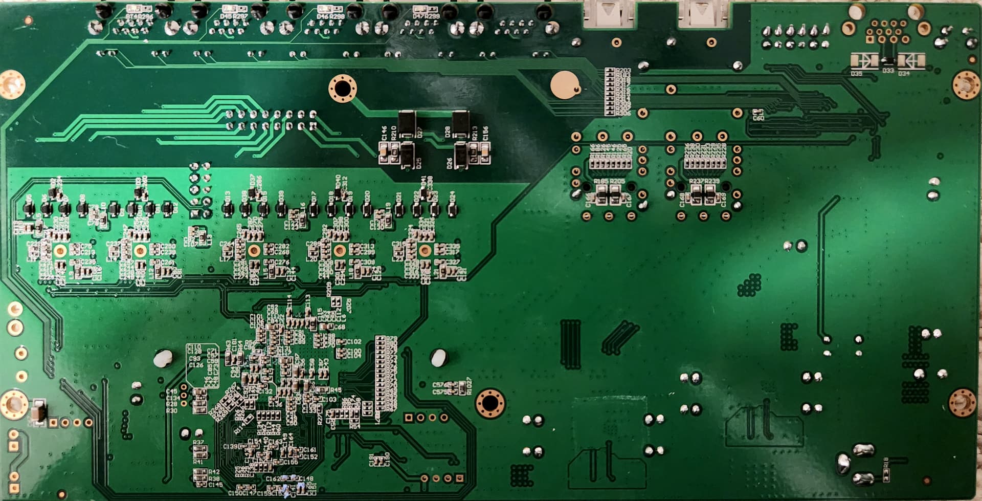
I imagine if I hook into the correct pins, I could get a terminal, but a cursory glance of the traces layout suggests that it's not conventional?
I'd really appreciate it if someone could label the traces so I could hook in (bottom right, right of the the black LED block.
My prime suspect would be J8(?), top middle, right to the flash chip, but J4 seems to be fully equipped (aside from populating the db-9 connector) as well (confirming the voltages recommended).
I've tried connecting at J4 with various things (buspirate, raspberry pi 3's serial port via terminal) with just GND, RX, TX and I've been getting jibberish @ 115200. I mean, I can tell it's sending something but it's not proper ASCII. Is there a common uart config used for these switches? 115200, stop bits, parity bits etc?
Here's some more pics I took with macro on the phone.
I'm guessing the issues with getting a good terminal @ J4 might have something to do with the missing diodes at the socket, D35 and D34, but I'm not sure.
You might find J4 has some TTL signals on it.
But I'd just put an RJ45 on that footprint encompassed by J4. That's exactly the same as the other Hasivo switches I've seen. It's an RS232 Cisco terminal connection.
It has the boot messages, and you can drop into the UBoot console from it.
EDIT: Just looked at the second PCB image. J4 is RS232 also. So you should just install RJ45 connector.
Haha, where were you a day ago .
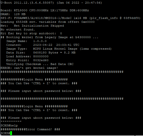
Yes, bought a cheap plastic pcb RJ45 socket and got onto uboot with the default password listed above.
Used a USB/console adaptor and finally figured the baud was *38400 of all things -_- (do these things auto-negotiate a speed or something?)
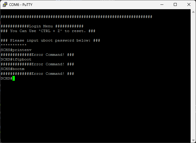
Kernal is fried. Can't seem to use the normal rtk_network_on without getting an "Error Command!" @dtw does knowing the load address and offsets help me if I were to do a firmware dump, merge it with a working version of the kernel, and then flash it back?
Also, pretty sure the jumpers @ J9 (top, right of the flash chip) lead directly to the chip, so could possibly use them to flash it rather than clamping on.
What voltages/tools should I use?
-_-
I'm not exactly sure what it means when even this doesn't work.
Like, I don't know if there something I need to unlock, or a jumper I need to bridge.
Is there a way I can flash uboot onto the flash chip directly? Or would I need a special uboot image with some config stuff in it to even talk with the Realtek9303?