Also burning this bin, SPI activity loop forever.
As I understand you burn only uboot. In this case asus/padavan uboot can't find valid firmware and start recovery mode. Asus recovery mode is specific. It start tftp server and wait client to load firmware. See/use Firmware Restoration or use tftp client. But pay attention that without restoring "factory" partition wifi will fail.
And why don't you use fulldump images from posted archive?
BTW do you have USB-to-TTL serial adapter? it's a "must have" thing for developers 
Forget that I have an ASUS router.
Let's say I have a evaluating board Mediatek with Chip MT7620
I have bournet this uboot link
Automatic TFTP would not start, or did not understand IP servers, and file name.
Using the keyboard, Option 2, I told IP servers and files, so I loaded with OpenWRT success.
I will try to rebuild uboot in the future for this problem, partly because he starts to 115200, then later changed to 57600
Wel Starting from consolle, I usually edit the file /etc/config/wireless, to enable the WiFi, but that file does not exist now.
I have build image, using preset, RT-AC51U,and after added Luci.
What is "Wifi 2.4G/5G default calibration data" and what are they for ?
Than forget of asus rt-ac51u openwrt image and start from openwrt wiki documentaion for developers ![]()
It's a fork of the same padavan project ![]()
Data for correct initialization of wifi devices. Without that data driver loading failed (see output of dmesg command). And as result there is no autodetected /etc/config/wireless config file.
[ 13.840035] mt76x0e 0000:01:00.0: ASIC revision: 76100002
[ 13.887393] mt76x0e 0000:01:00.0: Firmware Version: 0.1.00
There are custom firmware on the ASUS CPU ?
If I buy new CPU is different then This ?
[ 0.000000] Initrd not found or empty - disabling initrd
[ 0.000000] Memory: 58360K/65536K available (3920K kernel code, 191K rwdata, 896K rodata, 1192K init, 212K bss, 7176K reserved, 0K cma-reserved)
[ 0.753988] Creating 4 MTD partitions on "spi0.0":
[ 0.763561] 0x000000000000-0x000000030000 : "u-boot"
[ 0.774541] 0x000000030000-0x000000040000 : "u-boot-env"
[ 0.786076] 0x000000040000-0x000000050000 : "factory"
[ 0.797109] 0x000000050000-0x000001000000 : "firmware"
[ 0.811479] 2 uimage-fw partitions found on MTD device firmware
[ 0.823344] Creating 2 MTD partitions on "firmware":
[ 0.833256] 0x000000000000-0x000000198cfd : "kernel"
[ 0.844153] 0x000000198cfd-0x000000fb0000 : "rootfs"
[ 0.854971] mtd: device 5 (rootfs) set to be root filesystem
[ 0.868015] 1 squashfs-split partitions found on MTD device rootfs
[ 0.880409] 0x000000422000-0x000000fb0000 : "rootfs_data"
[ 13.906417] urngd: jent-rng init failed, err: 2
[ 13.991603] mt76x0e 0000:01:00.0: EEPROM data check failed: ffff
[ 14.015846] mt76x0e 0000:01:00.0: driver does not support default EEPROM
[ 14.029340] mt76x0e: probe of 0000:01:00.0 failed with error -22
[ 14.063688] rt2800_wmac 10180000.wmac: loaded eeprom from mtd device "factory"
This error ?
This router has welded RT7610 5Ghz Chip
I want use removable USB stick with same RT7610
If work also other USB AC 5GHZ stick.
In reference to this, what does put the "calibration data"?
There are custom firmware on the ASUS CPU ?
If I buy new CPU is different then This ?
If i use other type of USB WiFi Stick, need always calibration ?
What is calibration data ?
See /lib/firmware path. The firmware is the same for each type of chip.
USB stick and PCIE card usually have EEPROM chip on board with calibration data.
At least calibration data contain frequency and power calibration, MAC address and so on. Too many info for short message. You can see source of driver for details.
Hi Serge.
I'm not as good as springtales
I can not figure out how to put that map in the flash
Now I programmed uboot and more or less it works.
Do I have to join uboot with DD?
The thing that seems strange to me is that there are no partition.
binwalk MT7620_AP_2T2R-4L_internal_LNA_internal_PA_V15.bin

DECIMAL       HEXADECIMAL     DESCRIPTION
--------------------------------------------------------------------------------

binwalk MT7610E-V10-FEM.bin

DECIMAL       HEXADECIMAL     DESCRIPTION
--------------------------------------------------------------------------------
And the MAC ?
It should not be written into the radio chip ?
In mac is the name of the chip manufacturer.
Simply flash any full flash dump from
And what do you expect to find? It's only default calibration data.
Maybe this time I understood.
Each .bin file include Uboot, Wifi 2.4G + 5G default calibration + Firmware.
But i have to customize Uboot.
Then how can I join Uboot + Wifi 2.4G + 5G default calibration ?
I don't understand your question. I gave all information.If you want change dump than see flash layout. If you want change flash content from openwrt than use mtd-rw kernel module and mtd command.
gevagiorgio@PC-Ufficio:/mnt/d/Downloads/del$ binwalk fullflash-padavan.bin

DECIMAL       HEXADECIMAL     DESCRIPTION
--------------------------------------------------------------------------------
113296        0x1BA90         U-Boot version string, "U-Boot 1.1.3 (Feb 28 2016 - 06:19:08)"
327744        0x50040         LZMA compressed data, properties: 0x5D, dictionary size: 33554432 bytes, uncompressed size: 3427620 bytes
1499792       0x16E290        Squashfs filesystem, little endian, version 4.0, compression:xz, size: 8897609 bytes, 1660 inodes, blocksize: 131072 bytes, created: 2016-01-31 19:13:19
-
Where can i find the map of the partition locations?
-
Can you please help me understand how to build the semi full imagefile from pc? I need to reassemble it before flashing to the device.
Uboot and WiFi map -
If my routing have some problem, how to reduce RAM frequency ?
Register for RAM Speed are on the flash ?
In 4th message of this topic
Or more detailed:
0x00000000-0x0002ffff: uboot
0x00030000-0x0003ffff: uboot and firmware config data
0x00040000-0x0004ffff: factory data (wifi calibration)
                     0x00040000-0x000401ff: wifi 2.4G eeprom
                     0x00048000-0x000481ff: wifi 5G eeprom
0x00050000-0x00ffffff: firmware
All this information is here
Replace dump parts with yours data.
CPU and RAM frequencies are configured by uboot, so see uboot source.
Hi Serge
You are still available to help ?
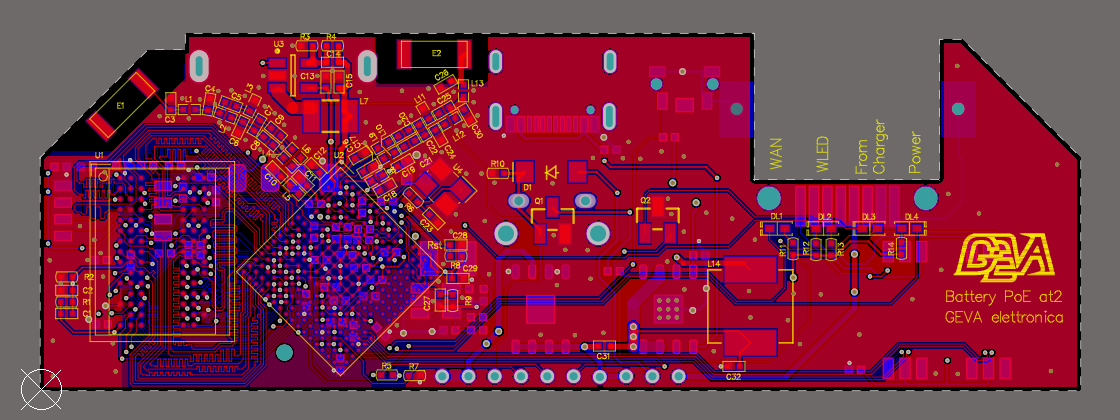
It took me a while ', but now I assembled my prototype.
I programmed the flash with your files fullflash-asus.bin
The flash is 16Mb, so your file has filled it all. WIndBond 25Q128JVS
At boot time, the micro reads the Flash, moves led some, but then nothing comes out from the console.
For me Consolle is TXD2 P13 and RXD2 R14
At boot, RXD2 is pulled low with resistor. (There is in the demo board, but nothing in the Mediateck documentation)
The Boot jumper are:
DRAM from Auto Detect (NOT PLL from EEPROM)
EPHY_LED (NOT JTAG MODE)
20MHZ xtal
DDR2 (CPU/3)
Normal mode boot from SPI 3-Byte address
What can I try?
Which help you mean?
Asus RT-AC51U don't have pins TXD2 P13 and RXD2 R14 so I don't understand this point.
My hardware is not ASUS.
It is custom board from My drawing.
I have consolle on the pin TXD2 (BGA pin P13) and RXD2 (BGA pin R14)
I do not know where the ASUS has the consolle.
RXD2/TXD2 is the consolle on the Ralink demoboard.
Did you connect rxd2 <--> tx of USB-TTL adapter, txd2 <--> rx of USB-TTL adapter, GND <--> GND of USB-TTL adapter?
I have Oscilloscope.
It is much better then USB Adapter
There's no activity.
One problem could be the DDR2 bus.
It is very difficult to do match length
If I put the jumpers on PLL from EEPROM
By changing some value in EEPROM I could make it go slower bus clock.
You know how byte change ?
It could be that Asus does not use RX2/TX2, there are many serials on the chip.
You know understand that port is used in asus ?
You can read text boot logs with Oscilloscope...Das ist fantastisch(c) ![]()
Usually all ralink/mediatek boards use uart lite as serial console.