I used Openwrt for many years, by flashing image via GUI. But for NEC Aterm WG2600HP3, I find the steps as shown below. But this device has actually no serial port and usb port, so I don't know how to do from step-4.
Setup TFTP server (IP address: 192.168.1.2)
Put initramfs image into TFTP server directory
Connect WG2600HP3 lan port and computer that runs TFTP server
You have to open the case and find the 5-pin through-hole header (J3) on the circuit board. The git commit, has the details of the pinout -- it is most likely a 3.3V serial interface. You'll solder some cables to connect between those pads and a standard USB-Serial adapter (such as this one, for example).
Thanks for your instruction. I guess what you meant is: J3 => USB => Serial, right ?
But I may need to give up. Japanese product is so high quality and precise that I cannot even open the case, even though I have done this on mobile and thin laptop before.
J3 is a set of through-hole pads on the PCB. I can't find a picture of that particular device, but here's an example of what I'm talking about from a different device. That is the type of serial connection that you need to use -- 3 important connections: Rx, Tx, and Ground.
The typical way of using those serial connections is via a USB-serial adapter (such as the one I linked earlier) which has its own serial Rx, Tx, and ground connections to wire to those on the router). The USB connection connects to your computer, and the device will show up as a serial device so you can use a serial terminal application on your PC/Mac/Linux system to communicate with the router.
Good news! Finally I can open the case. So I need your further help & instruction.
In the git commit you mentioned, I find below notes:
Serial console: 115200bps, through-hole J3
[ ] [GND] [ ] [TX] [RX] ----> DC jack
Power: DC 12V 1.5A
A) How can I know if the 5 holes on my router's board match above sequence from left to right or from right to left?
B) Then I just need to connect 3 wires, from GND to GND, TX to TX, RX to RX, right?
C) It mentions 'DC jack'. Do I need to provide external power supply ?
D) It mentions 'DC 12V 1.5A', so it is not 3.3V as you mentioned, and I need to find another similar USB-Serial adapter with 12V, right?
E) After finished, I just need to use a USB cable to connect from the adapter to the USB port of my computer, and my Ms. Windows would automatically treat it as an input port for display ??
The git commit is showing that the Rx pin is the closest to the DC jack. Tx is next to that. Then an unused pin, then ground, and finally another unused pin.
If this isn't clear, please post a photo of this board and I can label it (I don't have one of these devices).
GND <-> GND, but Tx <-> Rx and Rx <-> Tx.
You can think of it like your phone -- the speaker is the phone's output, but that goes to your ear (your personal input)... the microphone is the phone's input which needs signals from your output (your mouth).
This is the DC power that you would use to power the device normally... it should have a power adapter like pretty much any other device.
This is the rating on the power adapter to provide power to the entire router.
The signal voltages for the serial port (and many other things on the board) are done at 3.3V.
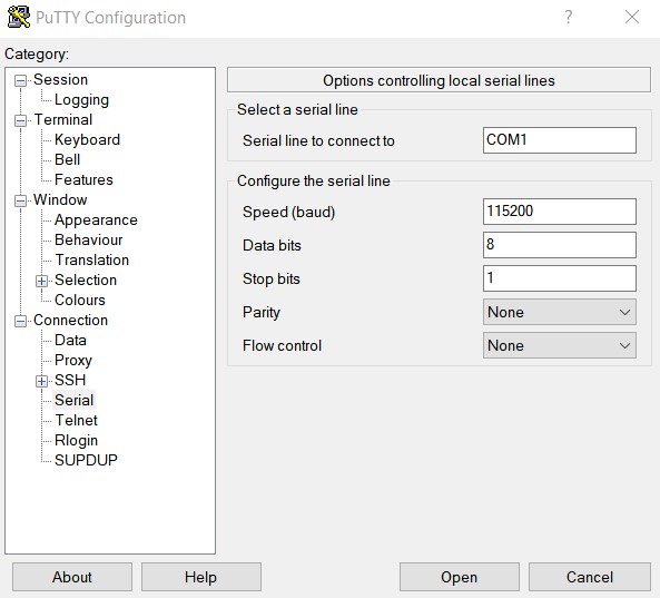
You'll connect the USB serial adapter to your computer by USB. Windows may need to install drivers, but that should happen automatically. You'll need a serial terminal application to use it. there may be one built into windows already, but many people like PuTTy for this purpose.
All of your explanation is very clear, and now I know how to digiest the relevant information. I will buy the adapter and try the surgery first, then update the result to you. The only thing I worry is to use Putty for Serial terminal device, since I have just experience in using Putty via Lan port, but never touched Serial terminal before.
Please help check if below steps are correct or not. And currently I have been stopped in step 6~7.
Connect wire between router and adapter as: GND <-> GND, but Tx <-> Rx and Rx <-> Tx.
Power-On the router
In this moment, the light of PWR is ON, and light of TXD & RXD is off.
Connect Adapter's USB port to my computer.
Should I also connect Router's LAN port to my computer ??
Configure Putty as your indication.
=> But Windows's Device Manager has only added USB device "FT232R USB UART", but not adding COM for it. So I forcefully configure Putty to the unused COM1
Open the Putty Session
=> Error message is pop-up: "Unable to open connection to COM1. Opening '\.\COM1': Error 2: The system cannot find the file specified".
Supposed to see the operation of Router ?
A. Put initramfs image (renamed to "wg2600hp3-initramfs.bin") into TFTP server directory (C:\TFTP-Root)
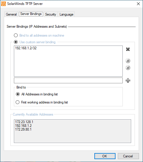
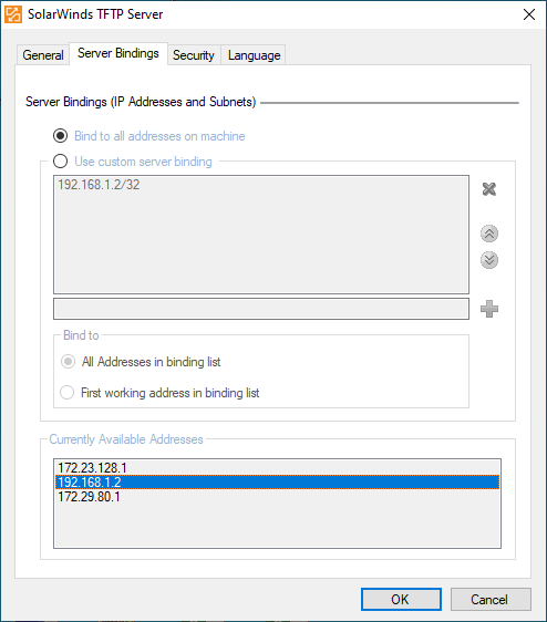
B. Configure SolarWinds TFTP Server to 192.168.1.2/32 as indicated (or use its default location 192.168.10.1 ??)
C. Re-start SolarWinds TFTP Server.
D. Power Off and On the router
E. Suppose to watche the booting process in the console, and I interrupt it by Esc key (password: chiron)
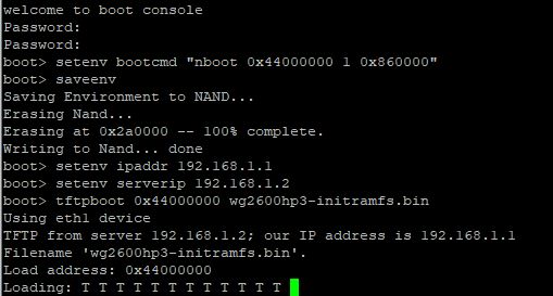
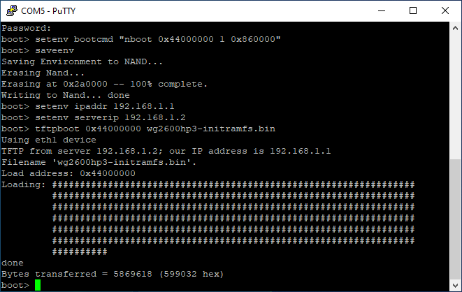
F. Execute the following commands via console:
# setenv bootcmd "nboot 0x44000000 1 0x860000"
# saveenv
# setenv ipaddr 192.168.1.1
# setenv serverip 192.168.1.2 (or 192.168.10.1 ??)
# tftpboot 0x44000000 wg2600hp3-initramfs.bin
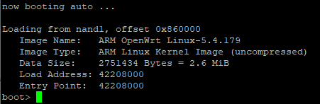
G. After booting OpenWrt initramfs image, backup SPI-NOR flash memory
H. Erase firmware partition
# mtd erase firmware
I. Run sysupgrade
COM1 and COM2 always exist in Windows, even though in most cases they are not usable since there is no hardware behind them. When you have the FT driver properly installed, a new port with a higher number will appear in the list you can select in Putty.
Also make sure to select the correct voltage on your usb2serial adapter (3.3V would be common, but that isn't explicitly spelled out for the WG2600HP3 in commit message or wiki, it 'could' also be 1.8 volts (less commonly)).
Your PC should be connected directly to your WG2600HP3 by ethernet (one of the LAN ports on that device). You should turn off wifi on your PC, too... this way there is only one network connection.
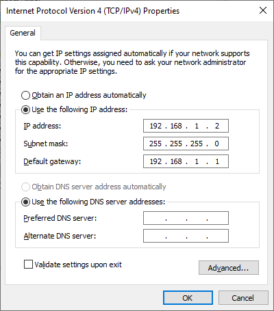
Yes. But you need to set your PC's wired ethernet connection using manual/static IP configuration (192.168.1.2/24).
Your instructions are very clear. I have followed all carefully, and turned off Windows' firewall, but still get the same result and the router cannot boot the file from TFTP server. For comparison, I can use TFTP client on Windows to get the file from the TFTP server on the same Windows.
Let me show you all configurations, including 2 TFTP configurations.
I didn't know latest ver of Windows will automatically turn on native firewall, even though I have installed 3rd party firewall. After doubly checking and turn off the former one again, this step has been "Done" successfully.
After "Done", I have power-off & on to reboot it, but I cannot browse 192.168.1.1 via browser, ssh it, or run below command under Normal mode or U-Boot mode in Console:
I am following on the official brief instruction, which hasn't mentioned bootm.
After running # tftpboot 0x44000000 wg2600hp3-initramfs-uImage and then # bootm, I can now "virtually" browse openwrt and enter ssh to execute # mtd erase firmware, but how can I really flash Openwrt image into the router ?
Once OpenWrt is running (in RAM), use scp to copy the previously downloaded sysupgrade firmware file to /tmp on the router. Then execute sysupgrade on the router with this file.
On your PC: scp firmware-sysupgrade-filename.bin root@192.168.1.1:/tmp
Then on the router: sysupgrade /tmp/firmware-sysupgrade-filename.bin
The sysupgrade program includes an erase. It isn't necessary to run the erase command.
Sysupgrade will install the final copy of OpenWrt to the flash then reboot to it. After the firstboot completes (about 2 minutes to format the jffs filesystem) the router is ready to configure and use.
ssh and scp are now built into Windows 10. Open a non-Administrator Command Prompt and cd to your Downloads directory where the .bin file is.
After sysupgrade *-sysupgrade.bin (not *-initramfs-uImage) and reboot, the router will boot back to U-Boot mode, but not Normal mode. This is the same result when I flash it via Luci GUI.
( Originally I want to flash *-initramfs-uImage first, but Luci GUI remind me that it seems to be an incompatible format and I need to select the "Forceful" option. Since I am not sure if it will cause my router to brick, I haven't yet tried this action.)

