I'm doing a bit of reseach on mesh networks, and managed to get my hands on two Carambola2-I modules. After purchasing some usb headers, antennas and AMS1117 power supply modules (4.0-12V to 3.3V) and soldering them onto the Carambola2, I intended to connect to them using a serial connection. Unfortunately, the modules weren't recognized by my PC (netiher windows nor linux found them).
My plan was to enable SSH on the modules using serial, then do the rest of the configuration over SSH. I've verified the power delivery works as intended. I've soldered the +3.3V to pin 51 on the Carambola, the GND connection to pin 46 on the Carambola, and the USB+ and - to pins 20 and 21 respectively.
Dunno about -I variant but have a look here at anything that says bootstrap and also the function of pin 13+11( or equivalent )... https://openwrt.org/toh/8devices/carambola2
Power supply
It is recommended to pin 50 and pin 51 for feeding the supply voltage. Use 100nF ceramic capacitors for decoupling.
Bootstrap
Bootstrap HIGH or LOW means that during bootstrap process (first few seconds when the device is turned on) these pins
need to be in the specified state. If pins are not in required state then device will not boot correctly.
Pins 35-41
Thanks for the quick response, I read about the bootstrap before getting the device, but totally forgot. I assume HIGH means I have to supply it with power (3.3V?) and LOW means I don't? Or should I connect LOW to ground?
As for pins 13 and 11, I believe they're correct as is (both disconnected). Unless I need to connect those to ground as well for option 0?
You too thanks for the quick response. I'm indeed using pin 51 for power delivery as suggested. As for Bootstrap, could you please explain exactly how that works (if you know)?
I assume HIGH means I have to supply it with power (3.3V?) and LOW means I don't? Or should I connect LOW to ground?
I am not sure about Bootstrap.
I mentioned the snipet because it says to use both 50 and 51, not just one.
Maybe you would get more answers in 8devices site for the hardware itself.
It seems odd to have to power the module using both ports, I assume it's supposed to say or (just like the instruction is missing the word use). Unfortunately the 8devices community forum is dead, so I was hoping there were some Carambola2 users over here. Thanks for the tip though!
I'm actually hoping to get the device to boot without user input. It should be possible to just supply power to the pins, if that's what is expected / required right?
I managed to solve the problem. For future reference:
After contacting 8devices for help, I managed to get somewhat further: the serial over USB is only on the carambola2-dvk. For the carambola2 (module), you should connect the serial adapter to the RX and TX pins (43 and 44 respectively) directly.
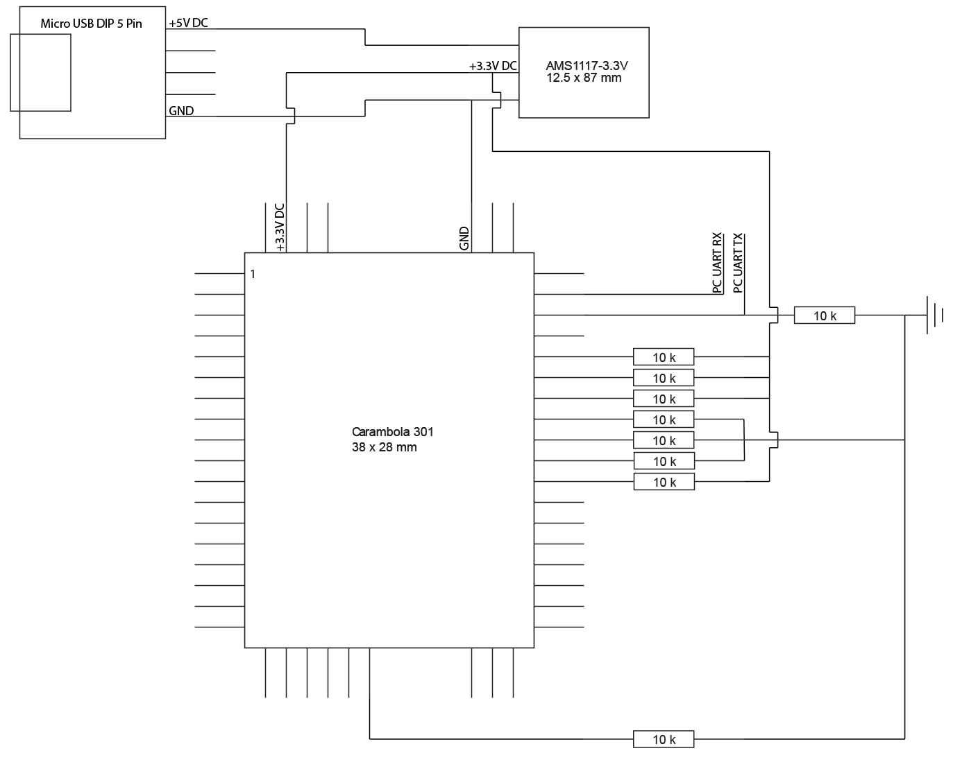
In my case, this still didn't work, because the signal strength was too low (I've been told). The solution for this was to attach a 10k Ohm resistor to the RX pin as well, and connect te other end of it to GND. I now managed to connect it over serial, and boot into failsave mode. The regular boot sequence still didn't work, as expected, because of the bootstrap pins.
Now for the fun part: soldering eight more 10k Ohm resistors to pins 24 and 35-41. All resistors were either connected to GND (where the datasheet indicated bootstrap L) or 3.3V (where the datasheet indicated bootstrap H). The carambola2 now started up no problem, and allowed me to actually enable wifi and connect!
In case anyone else runs into these problems, I've attached a schematic of my setup below. I'm no professional (I'm a software engineering student...), so it probably won't adhere to any conventions. It should be clear enough to use though.