I have the HH5A and am trying to use a max232 cable that's connecting using the serial cable.
I am not getting an output on the Putty, well its just a garbled block and then nothing else and the router lights don't come on so i guess its not switching on when shorted.
I know that the max232 works as i getting a reading from Putty when I plug in an old cable modem.
In short can I use a max232 cable for the HH5A or should I buy one of the suggested cables ?
I have tried to use the chopstick method to do the flashing.
Does your 'max232' cable plug into a USB socket or legacy 9 pin serial port on your computer?
max232 chip is used for converting between serial-RS232 and serial-TTL standards.
If it plugs into USB socket, it definitely won't work and you 'may' have fried the serial interface on the HH5A if unlucky!
I have a max232 board which plugs into serial port of an old PC, with other serial-TTL side wired to a HH5A. The max232 chip on the board also required external power. I never got it to work reliably with HH5A. I recall garbled output in PuTTY.
Update 2: I successfully used my max3232 board to load custom uboot. I discovered the max3232 board is prone to misinterpreting data 'rapidly' received from HH5A. I also discovered I had to increase the Vcc to 4.0 volts to the max3232 board for best results.
Don't apply more than 3.3 volts on the TX line (RX on the router). This means the power supply to the MAX232 chip should be 3.3 volts not 5 volts. There is the MAX3232 chip designed specifically for 3.3 volt operation. The regular MAX232 will likely operate at 3.3 volts but be out of specification.
First you could connect only the receive and ground and confirm that you see the bootlog on the PC clearly.
Thanks for the replies guys.
Just to confirm its a serial connection that plugs to the back of the computer.
I can still see BT page 192.168.1.254 so its not not bricked fingers crossed.
Regarding the PL2303 usb adapter is there one you can suggest on ebay link as I have been reading that some are fake and will not be able to work.
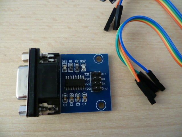
Here is a few pics of my max232 cable.
Yes. The parts you have should work, but yes you'll need to hook up the 3.3 volt power from the router. With a USB adapter you never hook up the power pin because you don't want to send power into the router, but here the situation is opposite. The MAX232 needs to be powered.
@bill888 : The adapter you have linked also has 4 connections so basically the red wire is the voltage wire and therefore not used?
The china one looks cheap enough.!
@mk24 : so if I were to supply the max232 from the router where would I supply it from, I mean do i just use another crocodile clip from the router to the max232 pin?
Or you could use a FT232RL module, from £2.99 sent from UK.
You'll need to solder wires or pins to it but in comparison to the soldering needed on the HH5A, its a doddle!
Type "USB To TTL FT232RL FTDI Serial Adapter Converter Module For Arduino 3.3V 5V Mini" or similar into Ebay.
But make sure you set it to 3.3v for the HH5A.
FYI the FT232RL also works a treat for flashing a Sonoff and an Arduino Mini.
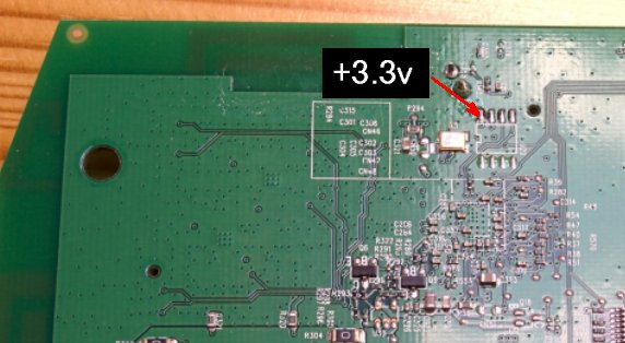
Yes, you would need to find a solder pad on the HH5A to provide +3.3v source for your max232 board.
Update: I thought I'd revisit my max3232 board. With just TX and RX pins shorted together, PuTTY was echoing garbage to what I was typing into the console. Raising the Vcc from 3.3v to 4.0v solved this problem. (I was using a variable voltage bench power supply unit)
I then wired the max3232 board to a spare HH5A. The only issue I encountered was when pasting the uboot file into PUTTY, instead of '*' filling the console, garbage appeared. I waited a minute for the transfer to complete and I was presented with the BTHOMEHUBV5A prompt. I was also able to execute the TFTP command to successfully load the LEDE install image for HH5A.
It would appear there is an issue whereby my max3232 board is not able to interpret data being transmitted 'rapidly' from the HH5A and to 'correctly' display it in the PUTTY console. Data sent to the HH5A appeared to be unaffected. The labelled max3232 chip may be a max232 chip or it is half faulty!
@bill888 : So basically you're saying that if I can supply the max232 with power (lets say from my old cable modem) I should be able to flash the HH5A?
Am I right in thinking (from your post) that the HH5A will not be able to power the max232?
Also how about the section in the guide where it says
> Go back to PuTTY. > Enter this command to upload the install image: > tftpboot 0x81000000 lede -lantiq-xrx200-BTHOMEHUBV5A- > installimage.bin; bootm 0x81000000
Did you do that part using the max232 or not ?
Thanks for following this up and posting back , even if it doesn't work for me at least I know you were able to do this.
The HH5A might be able to provide the +3.3 volts to your max232 cable if you want to try this first. If you are able to measure the voltage on your old cable modem, it will probably either be 3.3 or 5 volts - ensure both the +V and GND pins from the old modem is wired to Vcc and GND on your max232 cable. Use +5 volts at your own risk.
(The HH5A can't provide a +5v power source as far as I can tell. The 5 volts on the back of the USB socket only becomes live a few seconds AFTER switching on the HH5A)
I tried to solder the wires in but seem to have de-soldered the R78 spot !
Is there a way to solder it back so there is a solder spot like before or have I messed it up ?
I have tried to put a solder spot there but it does not seem to stick/hold in place.
This likely means you've got a "bad" board. The loopback test should pass without any strange behavior.
Note also that the DB-9 connector suggests that this is not a 3.3 V serial device, but an RS232 device. RS232, with its nominal +/-15 V levels, will likely fry any SoC. If you check a data sheet for a MAX3232 you will see that it drives bipolar output. SoCs are "rather intolerant" of both negative voltages, as well as over-voltage conditions.
Edit: As noted in the posts following, the MAX3232 is being used to adapt a PC serial port to unipolar levels, which is an appropriate use of the chip.
I can't see too clearly what you've lost there, but soldering SMD resistors by hand typically requires either a hot-air rework station or a very good soldering iron and a steady hand. A set of tweezers intended for working with SMD is very helpful, such as the EROP7SA. Paste flux and paste solder can be helpful, but tinning the lands is occasionally successful.
@jeff the DB9 connector was plugged into the PC's serial port, same as @cn90 . In my case, the loopback failed because there wasn't sufficient DC volts to the Vcc of the labelled max3232 chip (ie. I suspect it may actually be a max232 chip that requires at least 4 volt to work). But I agree with you that something is not quite right with the max3232 board I was using.
I thought you were using chopstick/nail method (from 1st post) ?
Almost impossible to repair lost solder pad. As pointed out by @jeff, any attempt to perhaps solder directly onto R78 is asking for trouble without the right tools. Perhaps try chopstick/nail method on R78 ??