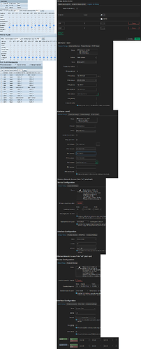
Asking for help regarding setting up VLAN

I'm using 23.05.5 on a Zyxel NWA50AX Pro.

Besides changing the fixed IP of the machine (and using external syslog to see what's happening) I did a reset to factory defaults.
I tried for a long time now but either I don't get it at all or my knowledge is too rusty.

What I want to achieve:

(1 physical WAN-Port)
2 WLANs, each associated with one VLAN-ID.

So WLAN1 => VLAN1 => WAN1 (ideally using IPv4 #1)
WLAN2 => VLAN2 => WAN1 (ideally using IPv4 #2)

My switch will deal with them.

I can't list the numerous things I've tried, up to desperately just trying this and that in the hope i randomly do it right. But I failed :slight_smile:

It sounds so super simple, yet i can't manage it. Thought this would be quick and Radius would take longer. Yet Radius already works...
Anyone willing to help? That'd be so grand!

PS: This is my first OpenWRT install. Previously only used DDwrt or the nasty cloud-thingies.

Not entirely sure what "associate" means here.

Not entirely sure what "using IPv4" means here.


If you want to create Tagged VLANs on an interface, go to:

Network → Interfaces → [Devices] → "br-lan": Configure...
→ [Bridge VLAN filtering]

and hit the Add button twice, give them IDs and mark them T on the port.

Next, you can go to

Network → Interfaces → [Interfaces]

Hit the "Add new interface..." button and you can configure an IP address, gateway and create a firewall zone fx. "wan1".

Repeat to make an IP interface on the other tagged vlan.


If you want to bridge a wifi network with a vlan, go to:

Network → Wireless → "wlan1": Edit
→ "Interface Configuration" → [General Setup]

In the "Network" drop-down, just select the interface you just created.

(Repeat for the other wlan.)


Alternatively, if you want to route a wifi network to a different subnet, that happens to live on a vlan, and you are fresh out of ethernet ports in the router to associate the wifi network with, go to:

Network → Interfaces → [Devices]

Hit the "Add device configuration", select device type "Bridge", and leave the bridge ports empty, just name it "br-wifi1" or something.

Then, you can go to Network → Interfaces → [Interfaces]

Hit the "Add new interface..." button and configure an internal IP address for the wifi network, and setup a DHCP server, and create a "lan1" firewall zone.

Next, go the the wireless network and select the freshly created interface in the "Network" dropdown.

Finally, go to Network → Firewall, under "Zones" find the "lan1" zone you just created, edit it, choose "accept" for input/output/forward, click the "masquerade" checkbox, and select "wan1" under "allow forward to destination zones".


Note: If you go with a routed setup, or rather 2x routed setups in one box, you will need a bit more than this to make sure that each wifi network is routed to their correct gateway etc. OpenWRT per default has just one internal router configured. But it comes with various facilities you can use to ensure correct routing, such as fwmark, ipv4 rules, kmod-vrf etc.

2 Likes

Wow, thanks for the very detailed help.Much appreciated!

Yet, whenever I activate vlan-filtering on the br-lan device I can't reach the AP anymore until I can revert the settings.
I tried doing all changes in one go before applying and everything else beside enabling filtering first.
But both ways net the same result.
Am I missing something here? I really start to feel dumber the longer I'll try to do that.

Just to be sure, I'll try to summarize what I try to achieve again:

2 WLANs:
one vlan-tagged (or not), the main network, the default.
one vlan-tagged, a guest network (IoT mostly). mostly isolated.

both use the same physical lan-port and the switch should do the job of denying vlan2 access to most ports and vlan1 (or untagged) should roam freely.

Did i miss anything or explained it badly?

Well if you add br-lan.1 and modify the "lan" interface you are connected with to use br-lan.1 and apply both changes.. Then you have to untag vlan 1 in your switch before it reaches your PC. Could that be it?

I struggled to understand if you wanted a bridged or a routed setup.

It helps saying you need an extra vlan for iot and guest.

Could use a description of the other 50% of your setup. The AP goes to a switch, sure, but how is the switch configured? And what's in the other end? :wink:

1 Like

Thanks again for your help :slight_smile:

I focussed so much on the AP, i neglected to check the switch :slight_smile:
It SHOULD be correct. See below.
So unless i screwed up here...

Bridged should be the better way.
And yes, sorry. Not used to asking for help. I should know better that there can't be too much information to be able to help ,-)
Instead of trying to summarize it (and forget half of it), i'll show the relevant bits:

I changed the IDs for a more distinct

And this is what I do on the AP (according to your step-by-step) which results in the ap being unreachable until it reverts back. Tried multiple times and it just won't do.

(can only include ONE inline-image, sorry for the cluttering)

If you want to stay connected to the Ethernet interface of the AP, and not just configure VLANs while connected via wireless, you could:

  • create vlan 1 as "untagged + pvid" on the port (u*)
  • switch the lan interface over to the new br-lan.1
  • save & apply

Then the traffic will still come in and out without any VLAN tags, so you don't have to worry about updating switch config etc. After that,

  • create vlan 2 as tagged on the port (t)
  • save and apply
  • create vlan 3 as tagged on the port (t)
  • save and apply

And use those two vlans to experiment with running things in tagged mode. Eg. create a new IP interface on top, assign a new IP subnet to it, save & apply. Go to the switch and see if you can untag the VLAN, connect some access port to the vlan, see if you can ping the new IP subnet from outside the AP, etc.

Least chance of locking yourself out. Otherwise just make sure that you can reach an IP interface via wifi as a backdoor. Or get a $5 RS232<->USB cable, those are great to have anyway.

1 Like

This was the problem. And I swear i did that before asking you, because i've read elsewhere that THIS is what people often forget. Sometimes I hate IT :slight_smile:

But now I have a way to go forward. Thanks a lot for your help, random internet stranger! Much appreciated!

I'm sure you will figure it out eventually on your own -
That said things move quicker with an extra set of eyes on the problem!

Yes! No need to stress the volunteers with having to use our imagination to figure out the setup hah

Noted !

Hah.

In OpenWRT you have:

id=666   port[eth0]=T
id=1337  port[eth0]=T

In the switch you have:

id=666   port[GE1]=T
id=1337  port[GE1]=u\*

Let's assume that GE1 <--> eth0 are connected with a cable.

Can you see the mismatch?

VLAN 1337 is not going to work, since the OpenWRT end emits and ingest frames with the "VlanID=1337" tag in the ethernet frame on the wire. The switch on the other hand is configured to strip and emit untagged ("u") anything belonging to VLAN 1337 internally. And also apply that vlan when a frame comes in without any tag (this is the "*" / PVID).


It looks like VLAN 666 should work though, at least between the switch and OpenWRT. They both tag it on the wire ("t").

If you want a switch port where your PC or laptop can actually talk to stuff on that vlan and eg. ping the IP interface (192.168.0.252/24), you would configure it like this in the switch, let's say for port 8:

id=666 port[GE8]=u*

And plug the PC into port GE8.

Or to show it another way, ie. the way the table looks in the switch screenshot:

GE8 Trunk 666UP

Same thing.

You can configure another port to reach vlan 1337 for testing, let's say port 11:

GE11 Trunk 1337UP

And then move the PC around between the two u* ports to get access from the PC to one or the other VLAN.


wan1 vs wan2.

You configured the same IP on both wan1 and wan2, namely "192.168.0.252".

This is not going to work - at least not in the default setup that OpenWRT ships with, where there is only one internal IP router to attach IP interfaces to. Can't have two IP interfaces with the same IP address/mask.

Just select "192.168.1.252" for wan2 instead, at least for testing purposes, until you can successfully ping both the wan1 and wan2 interface via a PC on switch port 8 / 11 (if you use the example switch port config provided above).

1 Like

np!

like and subscribe

1 Like

Just to make it really simple:

  • T means tagged on the wire

  • u* or UP means untagged on the wire


  • "Local" in OpenWRT means create a virtual device where the frames are raw (untagged) so you can attach an IP interface on top

  • "UP" in switch means create a physical port where you can attach a non-vlan configured device such as a PC into a VLAN. Then the PC can have an IP interface on the relevant network adapter


I think if one can remember that then it makes it a bit easier to plan out?

1 Like

thanks a lot again, you helped tremendously. And also maybe someone else equally blindfolded like I am ,-)

It sure does! Thanks!

Example documentation:

(looks like a lot, but each line is just a single config setting, so not terrible to go through)

OpenWRT AP

  • bridge "br-lan": vlan 1337 = eth0[u*] + Local
  • bridge "br-lan": vlan 0666 = eth0[T] + Local
  • interface "lan": device = br-lan.1337
  • interface "lan": ip = 192.168.0.252/24
  • interface "lan": gateway = 192.168.0.1 + dns = 192.168.0.1
  • interface "lan": zone = "lan"
  • interface "guest": device = br-lan.666
  • interface "guest": ip = 192.168.1.252/24
  • interface "guest": gateway = (none) + dns = (none)
  • interface "guest": zone = "guest"
  • wireless "wlan1": network = lan
  • wireless "wlan2": network = guest
  • firewall zone "lan": allow to zone guest
  • firewall zone "lan": allow input + output + forward
  • firewall zone "lan": masquerade = no
  • firewall zone "guest": reject to other zones
  • firewall zone "guest": allow output + forward
  • firewall zone "guest": reject input
  • firewall zone "guest": masquerade = no

Switch

  • GE1 = 1337UP and 666T
  • (GE1 connects to OpenWRT AP eth0)

  • GE2 = 1337UP and 666T
  • GE2 connects to firewall/router eth0

  • GE7 = 1337UP
  • GE7 used for temporarily connecting laptop into vlan 1337

  • GE8 = 666UP
  • GE8 used for temporarily connecting laptop into vlan 666

Firewall/router

  • virtual device "vlan1337" sits on eth0 with vid=1337, u*

  • virtual device "vlan666" sits on eth0 with vid=666, T

  • configure an IP interface with 192.168.0.1/24, call it "lan" (on dev: vlan1337)

  • configure an IP interface with 192.168.1.1/24, call it "guest" (on dev: vlan666)

  • configure an IP interface for WAN and default gateway

  • enable IP routing

  • enable DNS server, listen on 192.168.0.1 and 192.168.1.1

  • enable DHCP server on "lan" interface, range 192.168.0.128-192.168.0.254

  • enable DHCP server on "guest" interface, range 192.168.1.128-192.168.1.254

  • enable reverse path filtering / antispoofing, and

  • make firewall rules based on IP subnets:

#1 reject 192.168.1.0/24 -> 192.168.0.0/24
#2 allow 192.168.1.0/24 -> all
#3 allow 192.168.0.0/24 -> all
#4 drop

  • or do the same with zones - end result is a toss up, because: mostly zones contain 1 interface, mostly interfaces contain 1 subnet, ie. rejecting from "guest" to "lan" zones gets you almost the same end result as enabling antispoofing and rejecting from "192.168.1.0/24" to "192.168.0.0/24"

(zones end up pretty much being just a place to "name your subnet" in other words. if your firewall software actually supports concrete "named subnet" objects, eg. "lan" = "192.168.0.0/24"... the ruleset will look very similar, regardless of which method you use.)

(for example, opnsense has "Aliases" for naming subnets. so if that is your firewall, use that and do antispoof + ip firewalling. openwrt can only name zones, so if the firewall is openwrt, use zoned firewalling.)

Tests

  • Connect laptop to GE7, check dhcp works, ping 192.168.0.1, ping 192.168.0.252, nslookup openwrt.org 192.168.0.1

  • Connect laptop to GE8, check dhcp works, ping 192.168.1.1, ping 192.168.1.252, nslookup openwrt.org 192.168.1.1

  • Connect laptop via wifi to wlan1, same checks as above

  • Connect laptop via wifi to wlan2, same checks as above

  • Finally test ping 192.168.0.1 (lan) when connected via wifi to wlan2 (guest), should be rejected

Afterthought: Might want to call the subnets 192.168.66.x and 192.168.133.x to make it easy to remember which vlan they sit on? :thinking:

There, now you have a complete checklist to go by :smile:

1 Like

Jeez, you're a hero :face_holding_back_tears:
Thanks man!

1 Like

What makes you think we are done? :wink:

IF you want some final things you can do once everything is working:

  • Presuming the DHCP server is running on the router/firewall for all of the below

  • Disable the default DHCP server on Access Point "lan" interface, since you have configured a DHCP server on the router/firewall.

  • Disable routing between subnets in OpenWrt AP by deleting IP address and subnet on "guest" interface.

  • (edit: just to note that you cannot delete the "guest" interface in the AP entirely, since the wifi screen uses that interface to find out which bridge to attach the wifi-radio virtual ethernet device to, for some reason)

  • Set "forward" to "reject" in the firewall on the AP. IP forwarding generally means IP routing and you are bridging now.

  • Drop the zone rules that allow lan -> guest, routing happens in your router/firewall instead.

  • Double-check MTU settings; since the AP is not IP routing now, it will not IP fragment either. The vlan tag on the wire (802.1q) is 4 bytes, so physical interfaces should be at least MTU 1504 when they carry tagged VLAN frames. The virtual interfaces, and any physical interfaces that only carry untagged frames, can be left at the default MTU 1500.

  • Do a ping test with maximum frame size to verify the MTU settings work; there are 28 bytes overhead so from guest wifi to router/firewall fx.: ping -s 1472 -M do 192.168.1.1

  • Default openwrt configuration has some IPv6 routing on "lan" too, disable it: uci delete network.lan.ip6assign and uci set network.lan.delegate='0'

  • Turn the AP into an IPv6 "client" device (just like it is currently just an IPv4 "client" device): Create a new "lan6" interface (on top of same underlying device as "lan", ie. br-lan.1337). Set protocol to "DHCPv6". Set request-address to "try" and request-prefix to "no" and delegate to "off". Verify that the lan6 interface gets an IPv6 address from the router/firewall's pool after a little while.

  • This also gets rid of the AP using and delegating its own ULA prefix, instead it will use whatever it gets from your router/firewall.

  • Test that you can ping the AP from the router/firewall with ping -6 <AP's IPv6 addr on lan6 - choose a non-linklocal one>.

Enjoy :slight_smile:

Ha lol! Thanks man. Again a lot of helpful input. Yet you presumed falsely :slight_smile:
DHCP is already there on one of the win-servers :yum:

1 Like

That's just as fine as having it on the firewall/router. "advanced" steps above can still be applied (if a extra-clean setup is desired)

Will surely comb through, one can never be too thorough or clean :slight_smile:
Thanks man!

1 Like

This topic was automatically closed 10 days after the last reply. New replies are no longer allowed.