Add support for D-Link M30 (AQUILA PRO AI AX3000 Smart Mesh Router)

Hi,
I don't own the device but I played a little bit with the available firmware from D-Link. Some information:

  • FCC ID: https://fcc.report/FCC-ID/KA2M30A1/
  • Current work is based on M30A1_FW101B05(0725091522).bin, found it on D-Links Taiwan site
  • Seems like it's the same image crypto as for M32/R32 devices. The required keys are already included in the M32 GPL sources
  • I updated https://github.com/RolandoMagico/firmware-utils/blob/M32/src/m32-firmware-util.c to support the device and I can decrypt the firmware:
    ./m32-firmware-util M30 --DecryptFactoryImage M30A1_FW101B05\(0725091522\).bin M30A1_FW101B05\(0725091522\)_decrypted.bin
  • Difference from R32/M32: After the D-Link image header, there is a (sysupgrade??) TAR archive (containing the files CONTROL, kernel and root) instead of the plain data.
  • Router seems to be based on MT7981 CPU
  • Switch is MT7531
  • 512MB RAM
  • 128MB NAND flash with two UBI partitions with identical size. Looks like dual boot system. Config partition is also duplicated (Config1 and Config2)
  • Bootloader is probably U-Boot, at least there is a u-boot-env partition
  • No information about Wifi yet, according to the technical data, the router provides AX on 2.4 and 5GHz. /lib/firmware contains some MT7981* files, I assume MT7981 wifi similar to Cudy WR3000 v1

WIP: https://github.com/RolandoMagico/openwrt/tree/M30

2 Likes

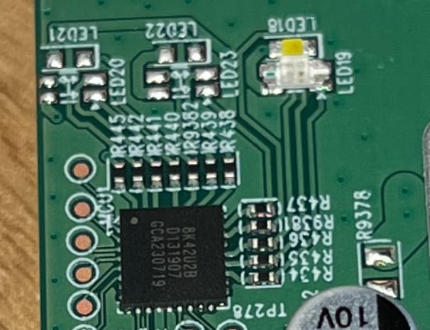
The LED(s) are connected to a chip with the following text on it:
8K42U2B
D131907
GCA230718

Does anybody have an idea what it is? Current assumption: Some kind of I2C controlled LED driver

Update: Assumption is correct. Sending specific data via I2C changes the LED color

Update 2: The LED supports 4 colors (red, green, blue, white), the I2C commands are similar to PCA9955B or PCA9685.

The LED controller communication is done with I2C address 0x40. To control the LEDs, three sequences must be sent to the chip.

Each sequence consists of a 3-byte "reset" command (0x00 0x81 0x0xE4) and a 14-byte "configuration" command:

  • Byte 0: 0x03 (Start Register)
  • Byte 1: 0x0C (Not sure what it is used for)
  • Byte 2: Must be set to 0x02 is the first sequence, 0x01 in the second sequence and 0x03 in the third sequence
  • Byte 3: Operation mode:
    • 0x00: Stops operation
    • 0x01: disable toggle mode
    • 0x02: toggle mode with 2 cycles (no ramp control)
    • 0x03: is toggle mode with 2 cycles (with ramp control)
  • Byte 4: Brightness of the red LED in the first cycle
  • Byte 5: Brightness of the green LED in the first cycle
  • Byte 6: Brightness of the blue LED in the first cycle
  • Byte 7: Brightness of the white LED in the first cycle
  • Byte 8: Cycle Frequency (Default 0x01)
  • Byte 9: Brightness of the red LED in the second cycle
  • Byte 10: Brightness of the green LED in the second cycle
  • Byte 11: Brightness of the blue LED in the second cycle
  • Byte 12: Brightness of the white LED in the second cycle
  • Byte 13: 0x87 (Not sure what it is used for)

What is not yet clear for me: Can I somehow configure the LEDs in the DTS if there is no driver available? How is this ussually handled?

Until now I didn't find a driver for the LEDs, so I'll try to implement one based on the following examples:

Current state:

  • Initramfs can be booted using U-Boot
  • Sysupgrade can be flashed from initramfs
  • LEDs are working using a device specific driver
  • LAN/WAN/WLAN working with device MAC adresses
  • Buttons (Reset, WPS, LED on/off) are working

Not working:

  • Flashing via recovery web interface or OEM web interface. Output during flashing:
Device romid:DLK6E6110001
 FW romid:DLK6E6110001
Device fmid:0x6E61 pv:1
 FW fmid:0x6e61 lpvs:1
 FW sid:0x8
 FW erase_start:0x2c0000
 FW erase_length:0x2d00000
 FW data_offset:0x2c0000
 FW data_length:0x2d00000
 FW header_id:0x4842
 FW header_major:0x2
 FW header_minor:0x0
 FW image_info_type:0x0
fw_upg: fw header(8) ok, but data error
fw_upg: fw upg NG, (remain len:47186046)
psock_readbuf:403 UPG FW Failed
1 Like

Update: Flashing via recovery web interface is now working as well. Turned out that the bytes at offset 0x0E and 0x0F are the 16-bit sum over the data area. Calculating it correctly allows flashing in the recovery web interface.
This is another difference to M32/R32, there the data area checksum was not considered...

2 Likes

oh wow, so this device is finally available :star_struck: I had been checking for the last months but eventually lost track of it... Just ordered myself one, though it will arrive only next year now.

I appreciate how we are finally way ahead of the game with supporting these; with the DAP-X1860 and COVR-X1860 it took around 1-2 years after initial release until they were sold off cheaply, even if it won't happen with the EAGLE and Aquila series at the same low prices, these things look quite cool, and may easily become the (both powerful and) stylish choice of gluon devices for those who can / want to afford it.

So they are very similar in software to the EAGLE series? Built by AMIT then as well, I remember when we reverse engineered the DIR-510 back then, they used an MSP430 microcontroller to handle power / LED signalling stuff, with a low-baud (bit-banged?) UART protocol between the MT7620 and the MSP430 to read battery status etc. Is there anything like that on the PCB? What is the package size of the 8K42U2B chip?

Could the LEDs also be controlled with simple bit swaps (full brightness / off), if the thing behaves like a PCA99xx expander? E.g. if the LED can be mapped to a GPIO, the expander is not an issue even for the kernel boot blinking sequence, I had successfully used the LED via I2C e.g. on DCH-G020 (ath79, with a simple GPIO-based I2C driver).

Looking forward to receiving my device, thanks for your work on this! :slightly_smiling_face:

Yes, but E30 and M60 are still missing...

I didn't compare the EAGLE wit the AQUILA series regarding OEM software, but from OpenWrt point of view, they have some common stuff (GPL sources, Mediatek), but there are also differences like dual partitioning the LED controller or the button to turn on/off the LEDs.

Didn't have a look at other stuff until now, main goal was to get OpenWrt working

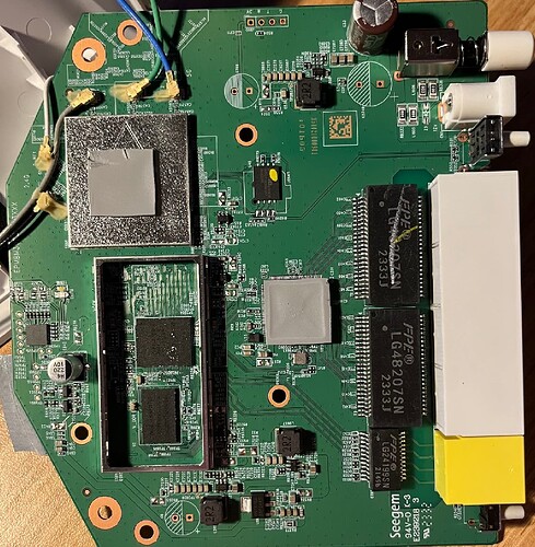
That's how it looks like (I hope the resolution is sufficient):
Bildschirmfoto 2023-12-26 um 17.08.35

In my tests I was not able to just swap bits, I always had to use the whole sequence to change the LEDs. But I didn't spend a lot of time for this until now, just use the existing command and adapted them to be usable in OpenWrt as kernel module.

PR is also there: https://github.com/openwrt/openwrt/pull/14273. Let's see if it get accepted or not.

Invested some more time and it looks like the whole I2C sequence is only required initially, afterwards, two commands (reset+control with byte 1 set to 0x01) are sufficient to enable/disable LEDs, for example:
"Reset" command:" i2ctransfer -y 0 w3@0x40 0x00 0x81 0xE4
"Control" command: i2ctransfer -y 0 w14@0x40 0x03 0x0C 0x01 0x01 0x00 0x00 0x00 0x00 0x01 0x00 0x00 0x00 0x00 0x87

Setting the brightness values also works with this two commands.

1 Like

I think it's curious they have two more channels of LEDs that are unpopulated (but they did not remove the resistors :joy: ), but the PCB is probably not the same as with the bigger variants (at least the cases look larger on the pictures).
Is there any unpopulated footprint for an 802.15.4 / matter module on this PCB? Or for an additional wifi chip, assuming they use DBDC here, and just an additional chip for the M60.

But we will see when those devices come out, as of now there is not even Internal Photos for the FCC filings listed, but probably within a few weeks (at least for M30 the 180 days of confidentiality will have passed).

Could not find anything about that MCU, at least Holtek and Gigadevice seem to have consistent markings on their devices, while Padauk would typically label them on the bottom of the chip... maybe some proprietary I2C PWM driver etc.? But at least it says MCU on the silkscreen, an there seem to be debug pads...

Full picture of the board:

2 Likes

Thanks, so they use a different board for the ZigBee / AX6000 variants then, makes sense.
Seegem looks quite Chinese for a "Made in Taiwan" product, but that's probably more about software backdoors than PCB manufacturing. Which again leaves hope for these devices to become very cheap one day, when Mediatek eventually drop the prices for these chips, there's not really much else on the PCB that looks expensive.

Actually, looking at current gluon devices from the filogic subtarget, I see e.g. the GL-MT3000 is already supported, but even a little more expensive to get at the moment. (edit: okay to be fair, there is the Cudy WR3000 which is even cheaper) And M30 may be easier to flash for average users, so let's hope this becomes even cheaper when the remaining Aquila devices show up on the market :blush:

The closest I could find related to naming of the LED controller is that:

1 Like

Awesome find, from the specs it indeed looks like 8K42 could be a 16-channel PWM version of 8K41, assuming all three LED footprints are designed for RGBW each at least 12 would be required. Couldn't find much official documentation / SDK / debugging hardware yet, but there is at least an application note with source code for a " WaterProof Touch Key Demo Board"...
Will have a look next year :slightly_smiling_face:

Currently working on the OEM web images. I can create them and I am able to flash them via OEM web interface but OpenWrt doesn't boot.
Everything is flashed to the second partition (ubi1), but during startup OpenWrt doesn't recognize the rootfs file system correctly:

[    0.768114] no rootfs found after FIT image in "ubi1"

Still no progress regarding the factory images. Currently I'm stuck with the partitioning in the DTS. The working state using only the "ubi" partition is:

			partition@580000 {
				label = "ubi";
				reg = <0x580000 0x3200000>;
			};

			partition@3780000 {
				label = "ubi1";
				reg = <0x3780000 0x3200000>;
				read-only;
			};

In the working case, I cannot download factory images as they would be written to the ubi1 partition, so I can just use flashing via recovery web interface or initramfs.

What I want to achive when flashing via OEM web interface is selcteding the active ubi partition during bootup depending on the kernel command line arguments, I tried this:

			partition@580000 {
				label = "ubi";
				reg = <0x580000 0x3200000>;
				compatible = "linux,ubi";
				openwrt,cmdline-match = "bootpart=ubi0";
			};

			partition@3780000 {
				label = "ubi1";
				reg = <0x3780000 0x3200000>;
				compatible = "linux,ubi";
				openwrt,cmdline-match = "bootpart=ubi1";
				read-only;
			};

But it results in this error:


[    1.002302] VFS: Cannot open root device "(null)" or unknown-block(0,0): error -6
[    1.009823] Please append a correct "root=" boot option; here are the available partitions:

OpenWrt is booting when changing label="ubi1" to label="ubi" and writing to the second partition, but then it's quite strange behaviour. Looks like no access to the U-Boot environment is present and ethernet doesn't work.

U-Boot environment:

MT7981> printenv
FW_RESET_FLAG=0
baudrate=115200
boot_by_part=if itest.s ${mupgrade_en} == 1; then aup;fi;if itest.s ${bootpart} == 0; then run set_act1; run ub0; else run set_act2; run ub1; fi
boot_by_tryactive=if itest.s ${sw_tryactive} == 0; then setenv sw_tryactive 2; setenv sw_active 1; saveenv; run ub0; else setenv sw_tryactive 2; setenv sw_active 2; saveenv; run ub1; fi
boot_rd_auto_sw_img=if itest.s ${sw_tryactive} == 2; then run boot_by_part; else run boot_by_tryactive; fi
bootargs=console=ttyS0,115200n1 loglevel=8 earlycon=uart8250,mmio32,0x11002000 bootpart=ubi0
bootdelay=2
bootfile=openwrt-mediatek-filogic-dlink_aquila-pro-ai-m30-a1-initramfs-kernel.bin
bootmenu_0=Startup system (Default)=run boot_rd_auto_sw_img
bootmenu_1=Upgrade firmware=mtkupgrade fw
bootmenu_2=Upgrade ATF BL2=mtkupgrade bl2
bootmenu_3=Upgrade ATF FIP=mtkupgrade fip
bootmenu_4=Http Upgrade=uip main; reset
bootmenu_5=Upgrade single image=mtkupgrade simg
bootmenu_6=Load image=mtkload
bootpart=0
con=0
en_wdt=wdt on 30
ethact=ethernet@15100000
ethaddr=be:e4:d5:0b:05:0d
fdtcontroladdr=5ff35220
fileaddr=46000000
filesize=7a73c0
fw_ver_a=1.01.05
fw_ver_b=1.01.05
i=7
ipaddr=192.168.200.1
loadaddr=0x46000000
mtdids=nmbm0=nmbm0
mtdparts=nmbm0:1024k(bl2),512k(u-boot-env),2048k(factory),2048k(fip),51200k(ubi),51200k(ubi1),256k(Odm),512k(Config1),512k(Config2),5120k(Storage)
mupgrade_en=1
netmask=255.255.255.0
power_on_rst_recov=setexpr i 8;setexpr con 1;while itest ${con} -gt 0; do  if gpio input 0; then   gpio toggle 5; else   setexpr con 0; fi; sleep 1; if itest ${i} -eq 0; then   setexpr con 0; else   setexpr i ${i} - 1; fi;done;if itest ${i} -gt 0; then  if itest ${i} -lt 4; then   setenv FW_RESET_FLAG 1; saveenv;  echo set FW_RESET_FLAG to 1;  gpio toggle 5;sleep 0.2;  gpio toggle 5;sleep 0.2;  gpio toggle 5;sleep 0.2;  gpio toggle 5;sleep 0.2;  gpio toggle 5;sleep 0.2;  gpio toggle 5; fi;else  uip main;fi
serverip=192.168.200.2
set_act1=if itest.s ${sw_active} != 1; then setenv sw_active 1; saveenv; fi
set_act2=if itest.s ${sw_active} != 2; then setenv sw_active 2; saveenv; fi
stderr=serial@11002000
stdin=serial@11002000
stdout=serial@11002000
sw_active=2
sw_tryactive=2
ub0=setenv bootpart 0; mtkboardboot; run ub0to1; uip main; reset
ub0to1=setenv bootpart 1; mtkboardboot
ub1=setenv bootpart 1; mtkboardboot; run ub1to0; uip main; reset
ub1to0=setenv bootpart 0; mtkboardboot

Environment size: 2376/262140 bytes
Still no progress creating the factory flash image. I'm able to download via OEM web interface and the upgrade is performed.
Then, there is a reset and I see also the power LED blinking in OpenWrt style instead of D-Link style. But it looks like it's running in failsafe mode. I see root@(none) instead of root@OpenWrt in the serial command prompt.
Any help is appreciated

Update: Found the problem :partying_face:
Similar to Netgear WAX220, the rootfs_data partition must be created during the first boot (see https://github.com/openwrt/openwrt/commit/fa9d977f979461628161085dcd0e9dd8b9e2c66b for details)

Next problem: OpenWrt expects the partition called "ubi" in the DTS. As there are two ubi partitions (ubi0 and ubi1) the partition for OpenWrt must be renamed to "ubi" to be able to be able to boot.
So currently if the OEM firmware is running on ubi0, ubi1 in the DTS must be renamed to "ubi". Vice versa if the OEM firmware is running on ubi1, ubi0 must be renamed to "ubi". Means I have two firmware images, depending on which partition the OEM firmware is running which works but doesn't sound like a good solution. Until now I didn't find a way to name both partitions "ubi" and select the correct partition based on the kernel command line arguments. I tried something like openwrt,cmdline-match = "bootpart=ubi0"; in the DTS but it seems to be ignored.
Is there any way to solve the problem? If not, another workaround would be to create OpenWrt images only for one ubi partition and flash the OEM firmware again so it runs in the other partition.

Have you tried uboot-envtools?

I already use them for setting the U-Boot variables related to the active boot partition. Is there a feature which allows me to switch the active boot partition from the device tree as well?

AFAIK it's not possible from dts.

@RolandoMagico
Great work! As always! :smiley:
If you are interested, a new firmware and the GPL have been published. :wink:

M30 A1 1.02 build 03 20231228 | Release Note
GPL M30 A1 1.xx