First of all thank you for the great work!
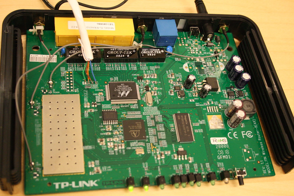
I have a revision 2.2 as well (Board revision 1.1). So i also bricked mine some days ago :-)
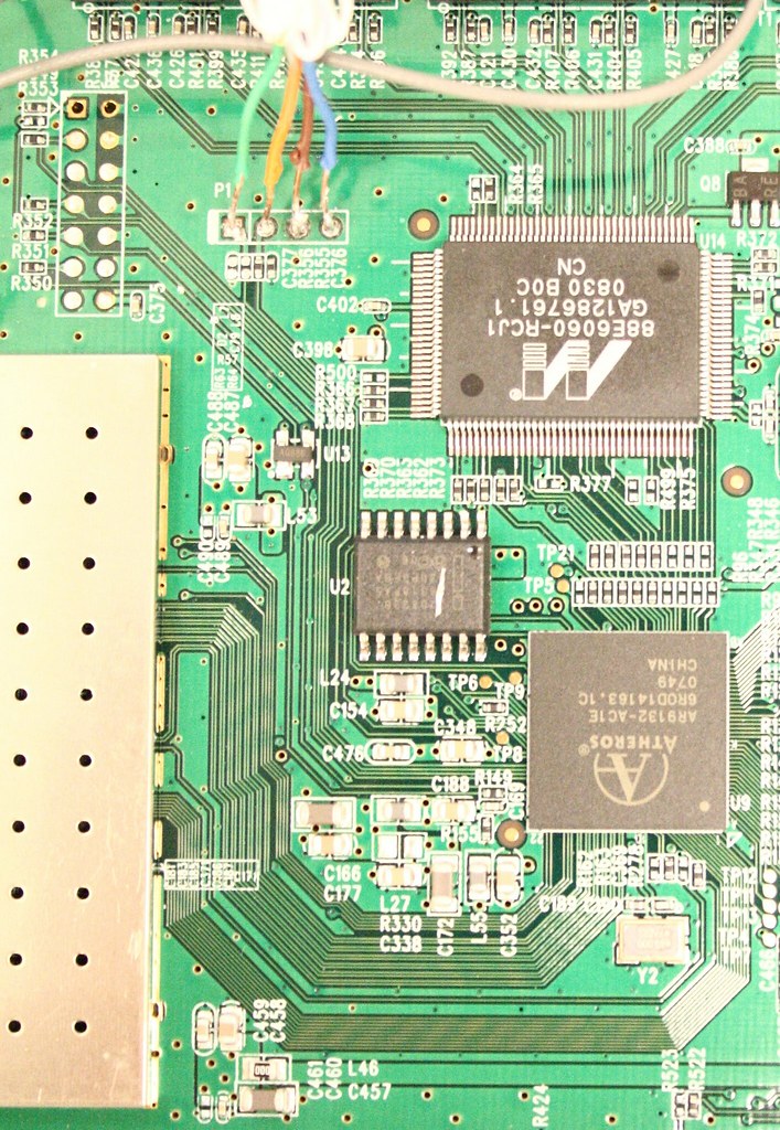
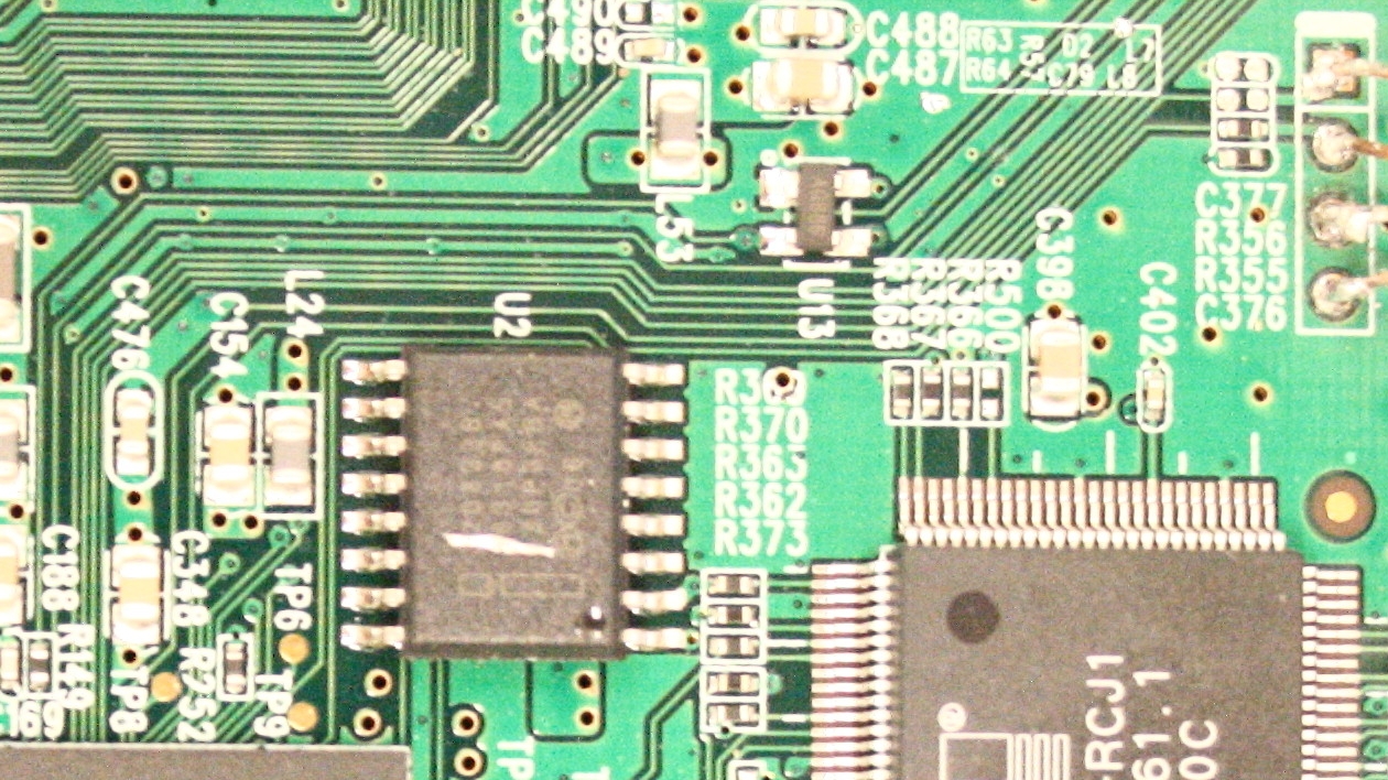
Lark studied your photos and says with confidence: P1 is RX, P2 is TX. R356 is all you should need to bridge.
I can confirm this. I use a self soldered USB to TTL converter (FT232RL based).
I have two outputs:
Uboot (9600):
U-Boot 1.1.4 (May  1 2008 - 19:25:20)

AP81 (ar7100) U-boot
DRAM:
sri
32 MB
id read 0x100000ff
flash size 8MB, sector count = 128
Flash:  8 MB
Using default environment

In:    serial
Out:   serial
Err:   serial
Net:   ag7100_enet_initialize...
No valid address in Flash. Using fixed address
eth0: 00:03:7f:09:0b:ad
eth0 up
eth0
Autobooting in 1 seconds, press "tp" to stop
## Booting image at bf020000 ...
   Uncompressing Kernel Image ... OK

Starting kernel ...

Linux version 2.6.28.7 (prisma@oimel) (gcc version 4.1.2) #1 Fri Feb 27 09:12:07 CET 2009
console [early0] enabled
CPU revision is: 00019374 (MIPS 24Kc)
Atheros AR9132 rev 1 (id:0xb5), CPU:400.000 MHz, AHB:100.000 MHz, DDR:400.000 MHz
Determined physical RAM map:
 memory: 02000000 @ 00000000 (usable)
Initrd not found or empty - disabling initrd
Zone PFN ranges:
  Normal   0x00000000 -> 0x00002000
Movable zone start PFN for each node
early_node_map[1] active PFN ranges
    0: 0x00000000 -> 0x00002000
Built 1 zonelists in Zone order, mobility grouping on.  Total pages: 8128
Kernel command line: rootfstype=squashfs,yaffs,jffs2 noinitrd console=ttyS0,115200 init=/etc/preinit
Primary instruction cache 64kB, VIPT, 4-way, linesize 32 bytes.
Primary data cache 32kB, 4-way, VIPT, cache aliases, linesize 32 bytes
Writing ErrCtl register=00000000
Readback ErrCtl register=00000000
PID hash table entries: 128 (order: 7, 512 bytes)
Dentry cache hash table entries: 4096 (order: 2, 16384 bytes)
Inode-cache hash table entries: 2048 (order: 1, 8192 bytes)
Memory: 29708k/32768k available (1818k kernel code, 3060k reserved, 332k data, 132k init, 0k highmem)
SLUB: Genslabs=6, HWalign=32, Order=0-3, MinObjects=0, CPUs=1, Nodes=1
Calibrating delay loop... 266.24 BogoMIPS (lpj=1331200)
Mount-cache hash table entries: 512
net_namespace: 480 bytes
NET: Registered protocol family 16
MIPS: machine is TP-LINK TL-WR941ND
NET: Registered protocol family 2
IP route cache hash table entries: 1024 (order: 0, 4096 bytes)
TCP established hash table entries: 1024 (order: 1, 8192 bytes)
TCP bind hash table entries: 1024 (order: 0, 4096 bytes)
TCP: Hash tables configured (established 1024 bind 1024)
TCP reno registered
NET: Registered protocol family 1
squashfs: version 3.0 (2006/03/15) Phillip Lougher
Registering mini_fo version $Id$
JFFS2 version 2.2. (NAND) (SUMMARY)  © 2001-2006 Red Hat, Inc.
yaffs Feb 27 2009 09:08:31 Installing.
msgmni has been set to 58
io scheduler noop registered
io scheduler deadline registered (default)
Serial: 8250/16550 driver1 ports, IRQ sharing disabled
Kernel (115200):
eth0: Atheros AG71xx at 0xb9000000, irq 4
Atheros AR71xx SPI Controller driver version 0.2.2
m25p80 spi0.0: unrecognized JEDEC id 898912
Atheros AR71xx hardware watchdog driver version 0.1.0
TCP vegas registered
NET: Registered protocol family 17
Distributed Switch Architecture driver version 0.1
eth0: detected a Marvell 88E6060 switch
dsa slave smi: probed
802.1Q VLAN Support v1.8 Ben Greear <greearb@candelatech.com>
All bugs added by David S. Miller <davem@redhat.com>
VFS: Cannot open root device "<NULL>" or unknown-block(0,0)
Please append a correct "root=" boot option; here are the available partitions:
Kernel panic - not syncing: VFS: Unable to mount root fs on unknown-block(0,0)
Maybe v2.2 (board 1.1) has a different flash chip (m25p80 spi0.0: unrecognized JEDEC id 898912)?
v2.2 has a Numonyx(INTEL) 320S33B chip...
BTW: I also had this strange output. That was when i used a self soldered COM TTL Adapter (MAX 323 based). I have no clue why this happend. some days later i bricked my serial port on my desktop :-(
So built an USB TTL Adapter based on this (modified for 3.3V)
(Last edited by prisma on 8 Mar 2009, 08:45)