So I'm trying to add a serial port connector to my C7 but I can't get it to show me anything. A few days ago I transplanted a 3 pin header from another circuit board to use in the C7 along with serial cable that I found for my raspberry pi. After soldering in the pin headers and connecting it, I found out first the cable had a fake FTDI chip in it and secondly it just flat out doesn't work in Windows 10. After re-assembling the router I found out that while it turns on and the power, star, 2.4 & 5 GHz, ethernet jack and WPS lights come on (no internet since I was using it as a WAP), it wasn't broadcasting SSIDs nor could I access it via it's IP. I also couldn't recover it via TFTP (edit: It doesn't even boot into recovery mode, it just ignores the button and boots up normally, I sniffed the packets). It was sending and (trying to) receiving packets though since there was activity with the LAN light. I just tried it again now (a few days later), using it as a switch and it works perfectly, so there's nothing wrong with it which is great, but I can't access LuCI or SSH via the IP I had assigned to it before all of this happened. edit: I ran a portscan of the 192.168.1.0 subnet and didn't find any IP registered to the C7, the WiFi doesn't work, yet it works perfectly as a switch.
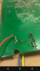
I bought a MicroUSB to Serial Breakout - FT232RL and soldered the Tx, Rx and Ground wires from the FTDI to the pads on the C7; connected the USB cable to my PC and let it install the drivers, then opened up PuTTY and connected to COM7; then I connected the power cable to the router and pressed the power button, all the lights came on but there wasn't any output from the console....
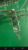
Thinking maybe I made a bad joint, I tested the continuity from each pin on the FTDI with the corresponding pin on the C7 and each one rang out! Then just to make sure that I wasn't shorting any pins, I tested the continuity between the Tx and RX pins on both the FTDI and the C7 and they were quiet. I did the same between Rx and Ground and it was quiet also. I repeated this with Tx and Ground and it rung out on both ends!
Now I'm not that great with electrical work (my dad is an electrician so I know a little bit), but is there supposed to be continuity between Tx and Ground (Pins 1 & 3), and not between Rx and Ground (2 & 3)? Also while the board was powered on and the FTDI was connected to my PC I decided to check the voltages and I got 2.121v DC for the Tx and 3.310v DC on the Rx, something tells me the Tx should be 3.3v also shouldn't it?
On a side note, I also have the JTAG pin headers soldered in, in case it helps with debugging WTF is going on.
(Last edited by brando56894 on 20 Mar 2016, 01:19)