OpenWrt Forum Archive

Topic: 703n no LED

The content of this topic has been archived on 28 Apr 2018. There are no obvious gaps in this topic, but there may still be some posts missing at the end.

This is my first topic so please excuse any mistakes such as wrong category.

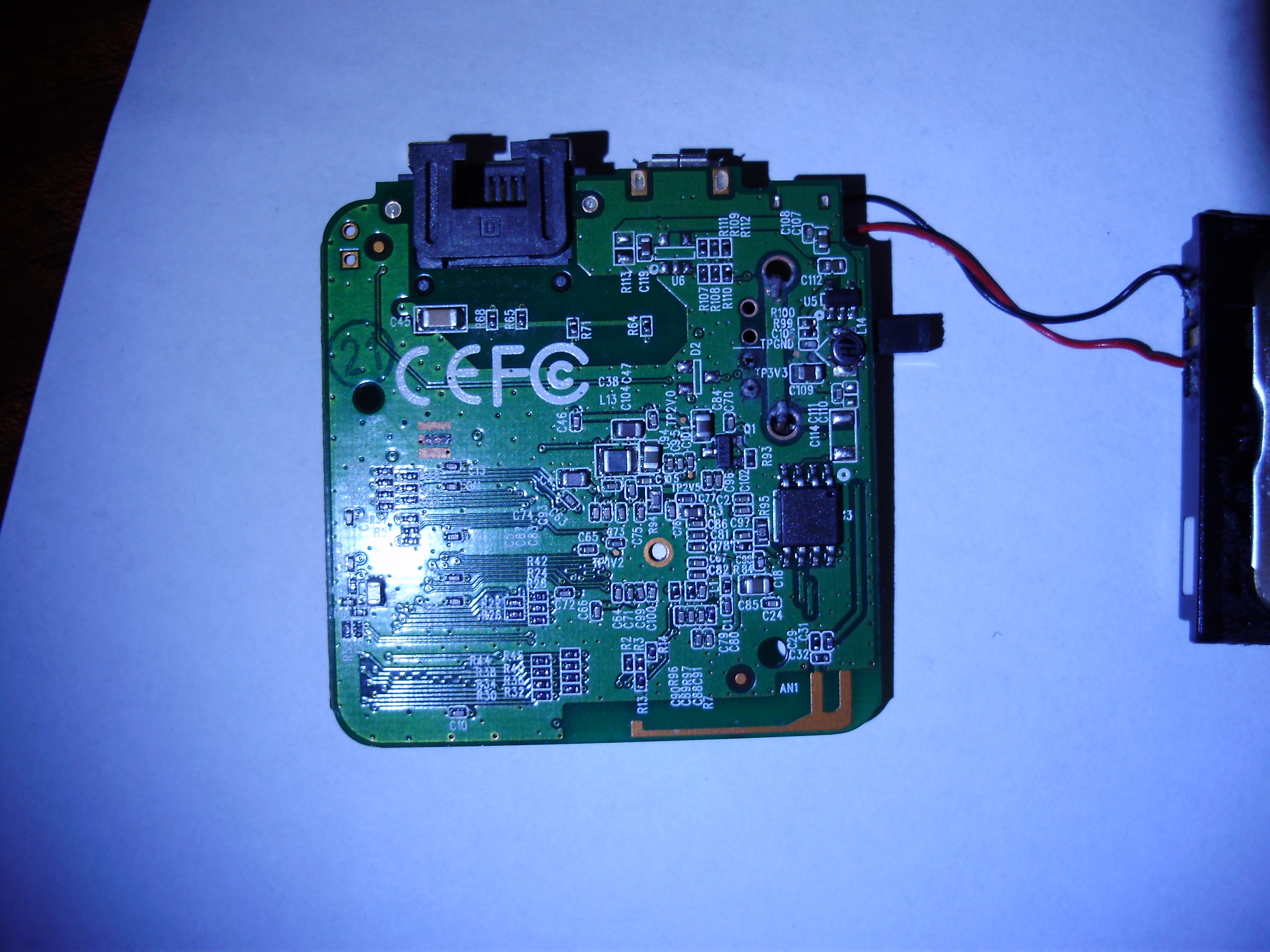
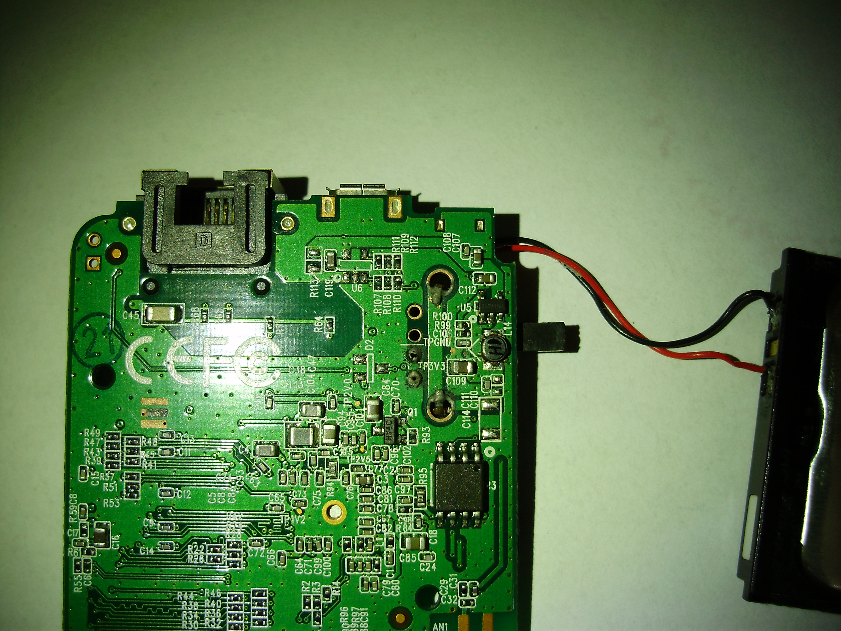
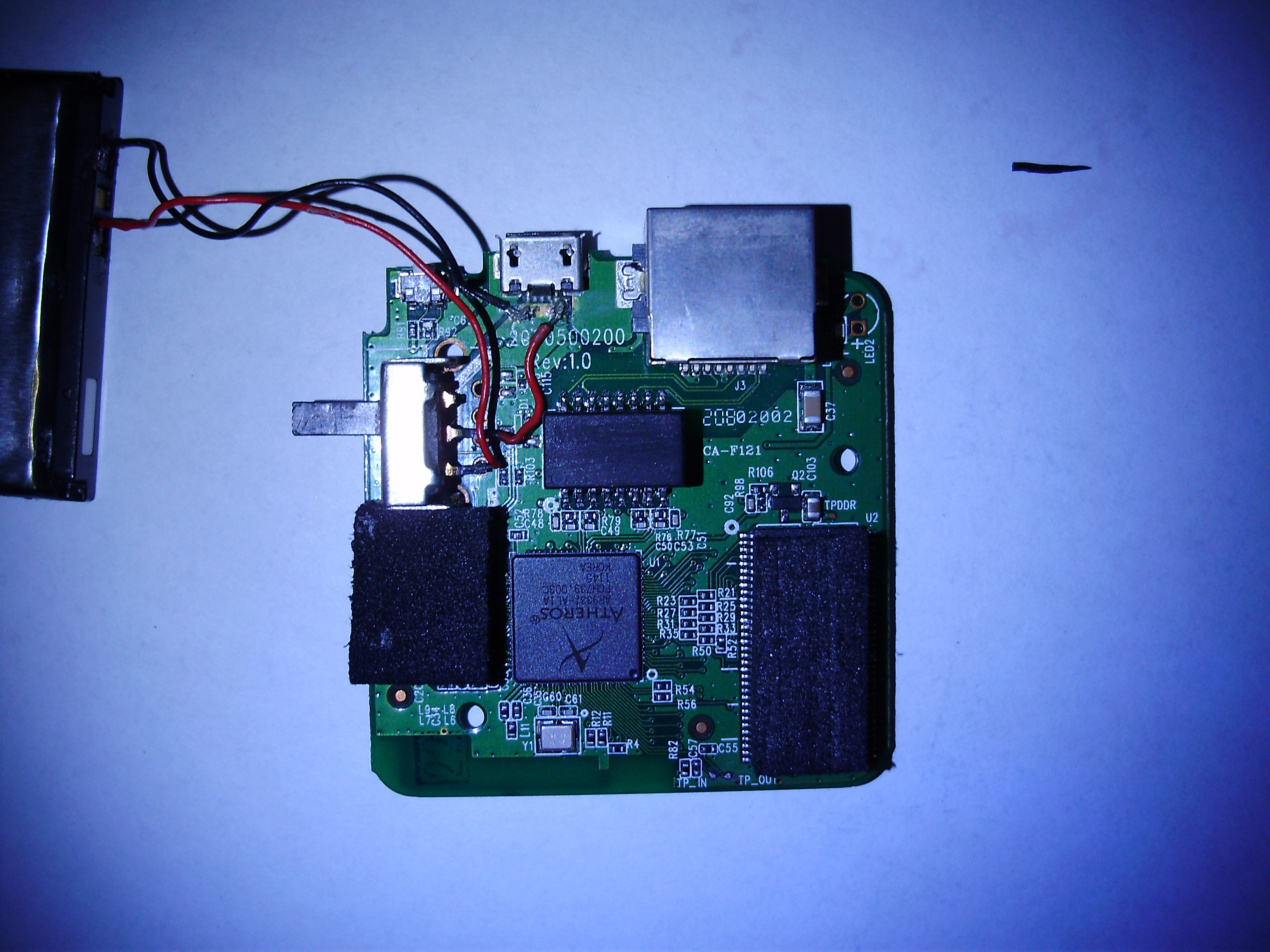
The thing is I tried to solder wires on my tp-link 703n in order to get a serial connection. I followed this guide  and everything went well. But when i tried to power on the router it doesn't start. No blue led, nothing.

Would you be kind enough to give me any piece of advice? Thank you.

Provide a high-resolution photo of the board with the solder connections.

you connected only gnd, tx, rx, right??

what adapter are you using?

I have the same issue.
Firstly, it worked very well, i got accsess to console by serial, but when i closed case, it stopped working, LED is not blinking now.
Using multimeter, i can see that internal voltage regulator gives 1.5v instead of 3.3v.
If i connect power using this serial line (3.3v), then router starts booting, but after all reboots due to lack of usb2ttl adapter's power.

vershinin wrote:

Using multimeter, i can see that internal voltage regulator gives 1.5v instead of 3.3v.

So, probably you have burnt it. Did you connect only RX/TX and GND? Which adapter are you using?

either burned it, or you ripped the traces off when you closed the case.

pepe2k wrote:
vershinin wrote:

Using multimeter, i can see that internal voltage regulator gives 1.5v instead of 3.3v.

So, probably you have burnt it. Did you connect only RX/TX and GND? Which adapter are you using?

I connected VCC 3.3v from my usb2seral adapter, and microusb cable connected to my desktop computer. May be, that is the reason why it burned out?

vershinin wrote:

I connected VCC 3.3v from my usb2seral adapter, and microusb cable connected to my desktop computer. May be, that is the reason why it burned out?

Yes...

vershinin wrote:

I connected VCC 3.3v from my usb2seral adapter

can I ask you if you read to do that in some tutorial/pictures and post a link to it? it will be useful to place a GIANT note on what one SHOULD NOT DO..

I followed the same guide as topic starter, except that i put VCC to LED2 + pad, because it is easier to solder. Btw, it worked for some time in this configuration until i closed the case.

I quote from that tutorial:

"
locate the GND, TX and RX on the board :

image...

solder some wire on it,
"

so no need to connect VCC (like on ANY self-powered device and serial adapter!)..

Yes, my bad. Looks like i need to build new power supply unit now smile

Here are some images taken with my camera which is not that great.

PunBB bbcode test
PunBB bbcode test
PunBB bbcode test

Also, I mention that after soldering the wires, I tried to power on the router but with no success. Quickly I de-soldered all the wires. I never tested it with my serial to usb (DKU-5 cable, if that matters).

I found that is not a 703n but a 702n sad   The two wires,black and red are there because of a mod: I added an internal battery, bst-38 model made by Sony ericsson. With a bit of sanding on the upper blue plastic, it fits perfectly for an autonomy of a few hours. You can also see the switch I fitted instead of the usb connector.


PS: problems with my internet connection is the issue for the long reply.Thank you!

(Last edited by dany_mid on 14 Jun 2013, 21:38)

Well well well......I found the problem! it  was a small piece of solder that made contact between 2 pins of  the RAM.
If anybody wants any more details related to the battery mod, just ask here what you want: pictures instructions or any bit of information.

Thank you everybody for your help!

The discussion might have continued from here.