OpenWrt Forum Archive

Topic: [How To] Home Automation - Relay Board controlled from Web page or SMS

The content of this topic has been archived between 17 Apr 2018 and 5 May 2018. There are no obvious gaps in this topic, but there may still be some posts missing at the end.

Instructions how to transform a cheap 110/220Vac Home PIR Motion Sensor in a "USB PIR motion sensor" for OpenWRT/Raspberry/Arduino


http://image.dhgate.com/albu_242448039_00-1.0x0/wireless-pir-sensor-for-home-security-motion.jpg

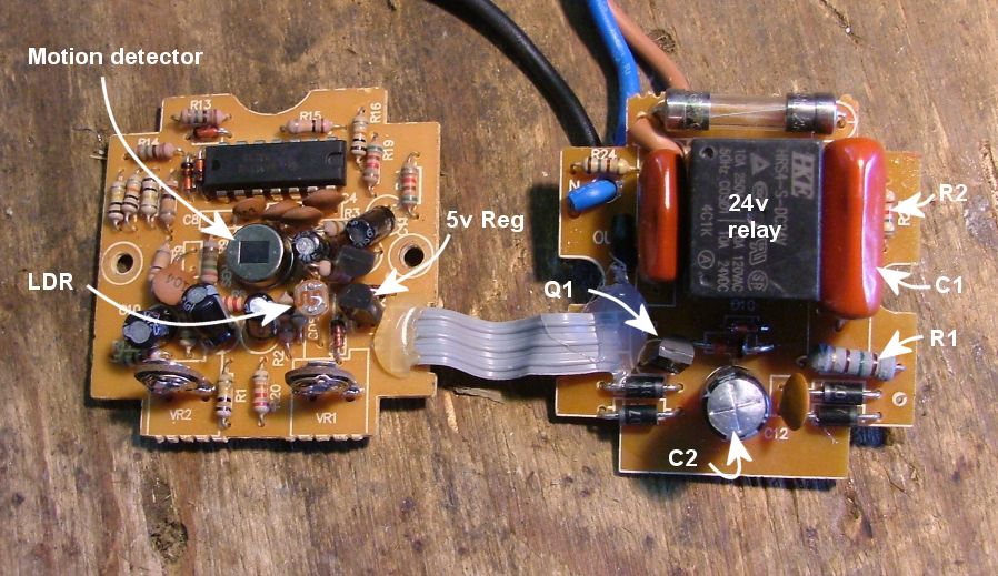
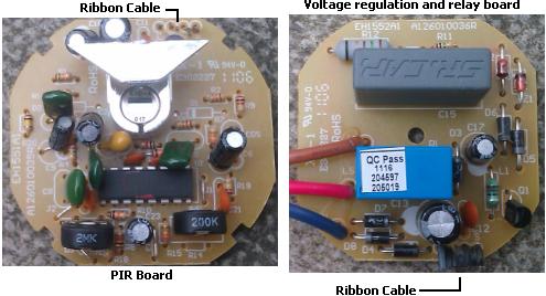
Open the device, inside you'll find two printed circuit boards: a PIR module operating from + 5V to 24V (see picture) and a relay module with transformer less capacitor power supply, to reduce the 110 or 220 Vac main line voltage to 24 Vcc non stabilized for the relay and 5-12 Vcc stabilized for the sensor board.

Some examples of internal PCBs:

model 1:
http://www.thebackshed.com/Windmill/articles/MotionLightImages/Dscf1274.jpg

model 2:
http://www.engineerathome.com/upload/automation_pir.jpg

model 3:
http://www.reuk.co.uk/OtherImages/internal-electronics-of-mains-powered-PIR-sensor.jpg


Cut the "three wires" ribbon cable that connects the two boards togheter, save the relay module for future use and keep the PIR sensor board.

The pin-out of my sensor board is Vcc , GND and output signal, from left to right as seen in the picture of the model 2, but it can be different for other boards even if similar, always check the labels on PCB.

Connect the +5V and GND of the PIR sensor board in parallel to the +5V and GND of the mouse board (+5V and GND from USB connector)

Optocoupler connection:

we need an optocoupler to interconnect sensor board output signal to the mouse board, the optocoupler I used is the 817b I found in an old USB modem.

http://www.dzsc.com/news/uploadfile/2012724155955543.jpg

Pin1 (anode): + 5Vcc
Pin2 (cathode):  output signal from sensor board
Pin3 (Emitter): GND
Pin4 (Collector): Mouse Button Switch (terminal connected to Integrated Circuit)

Note: the Opto-coupler can be easily found in many old devices like modems, UPS, serial interfaces.

Use triggerhappy to detect status of PIR motion sensor.

Enjoy smile

--------------------------------------------------------------------------------

Example of USB mouse circuit board to be used in conjuction of the PIR sensor (without leds):

http://www.lovisolo.com/asterisk/software/openwrt/Vodafone-Station-Home-Automation-Server/mouse.jpg

http://www.eehomepage.com/reports/20080214_teardown_pics/blockdiagram.jpg

(Last edited by pilovis on 5 Jan 2015, 18:17)

the finished job:

Note: the phone is connected to Asterisk (VOIP)

http://www.lovisolo.com/asterisk/software/openwrt/Vodafone-Station-Home-Automation-Server/server1.jpg

http://www.lovisolo.com/asterisk/software/openwrt/Vodafone-Station-Home-Automation-Server/server2.jpg

http://www.lovisolo.com/asterisk/software/openwrt/Vodafone-Station-Home-Automation-Server/server3.jpg

(Last edited by pilovis on 5 Jan 2015, 16:26)

probono wrote:

Isn't it this waste of a mouse PCB when the same could probably be done with just an ATTiny45 microcontroller and a few cheap parts as shown on http://blog.flipwork.nl/?x=entry:entry081009-142605

Anyone has got an old, unused or damaged, USB mouse.
I don't think many people have a microcontroller ATT available wink

(Last edited by pilovis on 5 Jan 2015, 15:56)

Great!!

(Last edited by hoatienii on 6 Jan 2015, 08:45)

hoatienii wrote:

Great!!

Please, learn how to quote correctly.
There's no need to quote the complete message, just to add one word by yourself.
Restricting the quotation to the necessary parts makes threads shorter and easier to read.

Thanks!

If you don't want or can't use a PIR sensor for motion detection, you can also use a USB webcam and "Motion" package.

opkg update
opkg install kmod-video-core kmod-video-uvc
opkg install motion

Those are the lines to be modified in "/etc/motion.conf" configuration file:

width 640
height 480
framerate 2
threshold 3000
output_pictures off           
ffmpeg_output_movies off
stream_maxrate 1
stream_localhost off
#
# command to be executed on motion detection, ex. /root/motion_detected.sh
#
on_motion_detected
/root/motion_detected.sh

Note: if you want motion to save captured images on motion detection (Warning: a lot of disk space is needed!), change the line: output_pictures off
to:
output_pictures on

To run motion simply use motion command

With Motion you can have both, motion detection and realtime image streaming (http://IP_ADDRESS:8081),  but it will increase  cpu and ram usage quite a lot.

(Last edited by pilovis on 5 Jan 2015, 22:56)

pilovis wrote:

Instructions how to transform a cheap 110/220Vac Home PIR Motion Sensor in a "USB PIR motion sensor" for OpenWRT/Raspberry/Arduino

http://www.dzsc.com/news/uploadfile/2012724155955543.jpg

... if you have a router that supports GPIO inputs (Vodafone Station does NOT) you can connect the PIR sensor directly to GPIO without using USB, simply connect the collector of the Optocoupler output transistor to a GPIO input pin (button active low image).

http://wiki.openwrt.org/_media/media/gpios-high_low.png

(Last edited by pilovis on 5 Jan 2015, 23:18)

Note:
changes from Attitude Adjustment to Barrier Breaker for Vodafone Station A.K.A Huawei EchoLife HG553 :

If you have installed Barrier Breaker, you should change the following lines (anywhere they appear):

/sys/devices/platform/leds-gpio.0/leds/HW553:blue:internetkey/brightness
/sys/devices/platform/leds-gpio.0/leds/HW553:red:internetkey/brightness

to

/sys/devices/platform/leds-gpio.0/leds/HW553:blue:hspa/brightness
/sys/devices/platform/leds-gpio.0/leds/HW553:red:hspa/brightnes

(Last edited by pilovis on 10 Jan 2015, 15:56)

IMPORTANT NOTE:

Since i discovered (it's my fault sad ) that during bootup all three channels are ON (cause the blue leds are off), I used the "red power led" as a consensus switch to Power (+5 Vcc) the "three cannels relay board" only after the full bootup sequence is finished.

To do so I used another relay channel (transistor+relay) and connected it to the red Power led cathode, than I put the following two lines in "/etc/rc.local" at the end of the file, just before "exit 0" command:

/bin/sleep 10
/bin/echo 1 > /sys/devices/platform/leds-gpio.0/leds/HW553:red:power/brightness

(Last edited by pilovis on 11 Jan 2015, 23:10)

Since mjpg-streamer documentation sucks, I'm putting here some useful information about it:


- to remotely capture a snapshot image from mjpg-streamer and save it to a jpg format:

wget http://user:password@mjpg-streamer-address:port/?action=snapshot -O output.jpg

- to remotely capture a streaming video from mjpg-streamer and save it to a file (mjpg format) format (open it with VLC):

wget http://user:password@mjpg-streamer-address:port/?action=stream -O output.mjpg

- to remotely capture a streaming video from mjpg-streamer and save it to a file (mjpg format) with a timestamp into the filename (open it with VLC):

now=$(date +"%Y-%m-%d----%H-%M-%S") ; wget http://user:password@mjpg-streamer-address:port/?action=stream -O output$now.mjpg

filename example: "output2015-01-13----01-10-13.mjpg"


- to put an overlay "time" on streaming video this is the mjpg-streamer "/www/webcam/index.html" modified file:

   <html>
      <head>
        <title>MJPG-Streamer</title>
<style>
    .container { position:relative; }
    .container video {
        position:relative;
        z-index:0;
    }

    .overlay {
        position:absolute;
        top:0;
        left:0;
        z-index:1;
    }
    </style>
      </head>
      <body>
        <div class="container">
            <img src="/?action=stream"/>
        <div class="overlay">
         <div style="position:absolute;width:290px;font-size:200%;font-weight:bold; background-color:lightgray; filter:alpha(opacity=60); opacity:.6;" id="time_span">  </div>

        </div>
    </div>

     <script type='text/javascript'>
timer();

    function timer(){
     var now = new Date,
         hours = now.getHours(),
         ampm  = hours<=11 ? ' AM' : ' PM'
         minutes = now.getMinutes(),
         seconds = now.getSeconds(),
         t_str = "&nbsp;" + [hours,
                  (minutes < 10 ? "0" + minutes : minutes),
                  (seconds < 10 ? "0" + seconds : seconds)]
                     .join(':') + ampm + "&nbsp;&nbsp;&nbsp;&nbsp;";
     document.getElementById('time_span').innerHTML = t_str;
     setTimeout(timer,1000);
    }

    </script>

      </body>
    </html>


- to launch mjpg-streamer from commandline:

mjpg_streamer -i "./input_uvc.so -f 5 -r 640x480" -o "./output_http.so -w ./www"

note: this command does not use the /etc/config/mjpg-streamer configuration file

or:

/etc/init.d/mjpg-streamer start

note: this command uses the /etc/config/mjpg-streamer configuration file


"/etc/config/mjpg-streamer" configuration file:

config mjpg-streamer 'core'
        option enabled '1'
        option input 'uvc'
        option output 'http'
        option device '/dev/video0'
        option resolution '640x480'
        option fps '5'
        option www '/www/webcam'
        option port '8080'
        option username 'user'
        option password 'password'


- to enable mjpg-streamer autostart at bootup:

/etc/init.d/mjpg-streamer enable


- script to remotely capture a streaming video for one hour from mjpg-streamer and save it to a file (mjpg format) with a timestamp into the filename, than stops and starts another recording, and so on (infinite loop)

#!/bin/bash
while :
do
now=$(date +"%Y-%m-%d----%H-%M-%S")
wget http://user:password@mjpg-streamer-address:port/?action=stream -O output$now.mjpg &
sleep 3600
ps -ef | grep wget | awk '{print $2}' | xargs kill
done


... more to come

(Last edited by pilovis on 13 Jan 2015, 07:13)

Baresip Openwrt SIP client

Baresip it's a good program but official documentation is hardly inexistent and sucks, like many small linux programs, as usual I had to figure out how to configure and use it.
How the hell do they create programs without writing a decent documentation?  mad  mad

- Prerequisites:

1) install Alsa and USB audio support
2) connect an USB audio adapter with a speaker and a microphone or a USB phone / headset (with microphone)
note: you might also use a USB webcam with internal microphone or just a USB microphone, in both cases you don't need an USB audio adapter but you won't have any speaker (one way audio)
3) adjust audio levels of speaker and microphone with command: alsamixer

note: see my other "How To" for detailed instructions how to configure USB audio: https://forum.openwrt.org/viewtopic.php … 63#p225463


- Installation and configuration of Baresip on Barrier Breaker (Baresip doesn't work on Attitue Adjustment: broken audio!):

opkg update
opkg install kmod-usb-hid
opkg install kmod-hid kmod-hid-generic
opkg install baresip baresip-mod-alsa baresip-mod-cons baresip-mod-evdev baresip-mod-g711
opkg install baresip-mod-stdio baresip-mod-uuid

Launch baresip once to generate the default configuration files on /root/.baresip:

baresip

after a few seconds stop it with ctrl+c
then you need to edit the configuration files

cd /root/.baresip

first edit "accounts" file

delete everything and insert the following line (use the values of your SIP accont):

<sip:user:password@sip-provider.com:port>;stunserver=stun:stun.ekiga.net

Note: you can add optional parameters to this line just by adding one or more of them with the following format:
<sip:user:password@domain;uri-params>;addr-params

example:
<sip:user:password@sip-provider.com:5060;transport=udp>;answermode=auto;stunserver=stun:stun.ekiga.net

list of optional URI params:

#    ;transport={udp,tcp,tls}

list of optional addr-params:

#    ;answermode={manual,early,auto}
#    ;audio_codecs=speex/16000,pcma,...
#    ;auth_user=username
#    ;mediaenc={srtp,srtp-mand,srtp-mandf,dtls_srtp,zrtp}
#    ;medianat={stun,turn,ice}
#    ;outbound="sip:primary.example.com;transport=tcp"
#    ;outbound2=sip:secondary.example.com
#    ;ptime={10,20,30,40,...}
#    ;regint=3600
#    ;regq=0.5
#    ;rtpkeep={zero,stun,dyna,rtcp}
#    ;sipnat={outbound}
#    ;stunserver=stun:[user:pass]@host[:port]


then edit  "config" file

delete everything and insert the following lines:

#comments added by pilovis
#
poll_method             epoll
input_device            /dev/input/event0                        #eventually adapt input device for your system
input_port              5555
sip_trans_bsize         128
audio_player            alsa,default                                  # audio speaker device
audio_source            alsa,default                                 # audio microphone device
audio_alert             alsa,default                                   # audio ring device
#
# if you want to use more than one audio device you need to use: alsa,default:CARD=devicename
# to discover device name use command: aplay -L
# -----------------------------------------------------------
audio_srate             8000-48000
audio_channels          1-2
rtp_tos                 184
rtcp_enable             yes
rtcp_mux                no
#jitter_buffer_delay     15-35  # uncomment this line only in case you use an external voip provider and you experience high ping latence
rtp_stats               no
dns_server              8.8.8.8:53                                   # use your preferred DNS server
module_path             /usr/lib/baresip/modules
module                  stdio.so
module                  evdev.so
module                  g711.so
module                  alsa.so
module                  stun.so
module                  turn.so
module_tmp              account.so
module_app              contact.so
module_app              menu.so
natbd_server            creytiv.com  # I'm not sure this line is necessary when you set "stunserver" option on user account
                                                   # and/or for local accounts: <user:password@localhost>
natbd_interval          600             # same as above, you might try to comment "#" both lines and test if baresip works
# eof

Launch Baresip:

baresip

then press "?" for all available commands

-------------------------------------------------------------------------------------

- Baresip remote audio monitoring

Make an automatic SIP phone call with the following command:

(/bin/echo sip:other-user@voip-provider.com; /bin/sleep 60; /bin/echo q) | /usr/bin/baresip -f /root/.baresip -e d

Note: "sleep 60; echo q" set the total call duration time at 60 seconds including ring time, after that "quit" command is sent to baresip, even if the remote party has not answered the call yet.

When the remote party answers the phone, he/she hears the ambient audio captured from the local microphone, also if he/she talks, his/her voice is sent to the local speaker (if connected and active).

-------------------------------------------------------------------------------------------------

- Launch Baresip as a daemon and configure it to auto answer all incoming calls

first configure baresip for auto answer all incoming calls by editing the "/root/.baresip/accounts" file as the following:

<sip:user:password@sip-provider.com:5060;transport=udp>;answermode=auto;stunserver=stun:stun.ekiga.net

then launch it as a daemon with the following command:

/usr/bin/baresip -f /root/.baresip -d

then try to call your local sip account, baresip won't ring but will answer the call and will start streaming the local audio to you (remote caller), same as above, if you talk,  people near to the openwrt router will hear your voice through the speaker (speakerphone mode)

NOTE: if you use baresip as a daemon and you also want to issue an automatic call from local (openwrt) to remote (eg.: your mobile), you should change the previous auto call command to the following:

(/bin/echo sip:other-user@voip-provider.com; /bin/sleep 60; /bin/echo b) | /usr/bin/baresip -f /root/.baresip -e d

basically here we are sending "b" command (HANGUP CALL) to baresip instead of "q" (QUIT BARESIP) because we want to keep baresip running in background.

If you want to use a USB Voip phone or a USB headset but you want to have a separate speaker that rings for the incoming calls, you need an extra USB audio adapter for the speaker, alsa will recognize it with a different device name, then you just need to modifiy "config" file as the following:

audio_player            alsa,default:CARD=headset_devicename
audio_source            alsa,default:CARD=headset_devicename
audio_alert             alsa,default:CARD=other_devicename

note: to find the two device names launch command: aplay -L 
----------------------------------------------------------------------------------------

- USB Keypad

if you connect an USB numeric keypad to your router, you can use it to answer the incoming calls (Enter Key) and/or to dial phone numbers followed by "Enter" key to start the call.
To hangup/cancel the call press "Del" key.

Note: if you want to use the keypad to accept incoming calls by pressing "Enter", you need to modify the account configuration file as the following:

<sip:user:password@sip-provider.com:5060;transport=udp>;answermode=manual

http://www.lindy.co.uk/images/usb-numeric-keypad-p763-1172_zoom.jpg

If you use a USB Phone you don't need the USB audio adapter.

http://blog.ashfame.com/wp-content/uploads/2008/02/usb_phone.jpg

if you install "kmod-usb-cm109" you can use some (old) USB Voip phones with support of their integrated keys, like
KIP 1000, G-talk , Atcom au100, Allied-Telesis Corega USBPH01, same for "kmod-usb-yealink" that support Yealing Voip phones.

http://www.komunikate.eu.com/images/kip1000.jpg http://www.voicesource.co.za/images/au-100.jpeghttp://i00.i.aliimg.com/photo/v0/493348222/Original_yealink_wireless_voip_usb_skype_phone.jpg_220x220.jpg

NOTE:

if you have installed Asterisk11 on the same router and you want to connect Baresip to local Asterisk, this is the account configuration example:

<sip:user:password@localhost>;answermode=manual


- To start Baresip at bootup but only after Asterisk has fully started, add the following line to /etc/rc.local:

/bin/sleep 10
/etc/init.d/asterisk start
/usr/bin/baresip -f /root/.baresip -d &&
exit 0

Don't use /etc/init.d/baresip enable or start, cause is broken (config path missing) and will not start at bootup nor will launch baresip daemon mad mad

(Last edited by pilovis on 31 Jan 2015, 16:11)

Basic Authentication on uhttpd

To add a password to uhttpd (web page access) do the following:

uci set uhttpd.main.config=/etc/httpd.conf
uci commit uhttpd
echo "/:root:password" > $(uci get uhttpd.main.config)
/etc/init.d/uhttpd restart

(Last edited by pilovis on 23 Feb 2015, 06:59)

Version 2.0

- Wan/Lan/WiFi connectivity
- 1 Channel relay output (1600W:2000VA MAX)
- 1 Channel Hi Pot Led spot light
- SMS (GSM dongle) and Internet (Web page) channels control (ON/OFF, Status, Router reboot)
- Motion detection (webcam)
- Remote streaming video control (wan/lan/internet)
- Remote streaming audio control  (wan/lan/internet)
- Programmable Phone alert (automatic phone call on event / status change)
- Programmable  SMS alert (SMS on event / status change)
- Programmable email alert (mail on event / status change)
- Restore previous channels state on reboot (restart/crash)

Notes:
1 Old Vodafone Station (no need of external Overlay/Extroot - internal 16 MB flash + 64 MB ram + 2 USB2 ports)
1 USB Webcam with built in microphone + 1 button (programmable)
1 USB 3G /Hsupa/UMTS/GSM dongle (included with Vodafone Station)
3 x 3V Arduino Relay boards  (2 external "NAND configuration" for output channel + 1 internal for spot light)
1 automotive Led spot light 12V - 24 leds - 12W
1 power supply 12Vdc 2A  (included with Vodafone Station)
1 power supply 4.5Vdc 0.5A (for relay boards)
Optional: external GSM/UMTS antenna 2db

Installed software:
OpenWRT Barrier Breaker (USB, Video, Audio, Led, 3G support)
Triggerhappy
Gnokii
Alsa
Baresip
Motion
Mini-sendmail
Luci
Optional: nano, mc, htop, vsftpd, ddns suppport

Total power consumption:
12W/h idle state, all channels OFF
25W/h all channels ON (led spot light ON)

Total cost: 65 Euro


http://www.lovisolo.com/asterisk/software/openwrt/Vodafone-Station-Home-Automation-Server/relay2a.jpg

http://www.lovisolo.com/asterisk/software/openwrt/Vodafone-Station-Home-Automation-Server/relay2b.jpg

http://www.lovisolo.com/asterisk/software/openwrt/Vodafone-Station-Home-Automation-Server/relay2c.jpg

(Last edited by pilovis on 23 Feb 2015, 23:42)

Great job. Thanks for share it.

Another idea for reuse old hardware is... use Bluetooth dongle in OpenWrt to connect to a old smartphones (like nokia), using bluetooth "handsfree profile" you can receive and make calls, identify caller id, etc..

KHAN85 wrote:

Great job. Thanks for share it.

Another idea for reuse old hardware is... use Bluetooth dongle in OpenWrt to connect to a old smartphones (like nokia), using bluetooth "handsfree profile" you can receive and make calls, identify caller id, etc..

Bluetooth is broken on Attitue Adjustment and Barrier Breaker, it doesn't work.

(Last edited by pilovis on 24 Feb 2015, 10:01)

Burglar alarm with motion detection
SMS + eMail + phone call on triggered allarm
SMS & Web remote control
Remote Audio & Video monitoring
1 channel output 1500 W max

Total cost = 70 Euro
Details & instructions @

Youtube video:
https://www.youtube.com/watch?v=nSt9eXwbLkk


http://www.lovisolo.com/asterisk/software/openwrt/Vodafone-Station-Home-Automation-Server/antifurto.jpg

(Last edited by pilovis on 2 Mar 2015, 15:39)

Hi, I started to build Home Automation Based on WR841ND TPLINK.
My aim is to control Garage Doors.

I use GPIO to control Relays, they are Active Low.
At the boot time, all leds are ON (and so GPIO to GND) during 1 second. the problem is that they open my garage door => Not really secure in power on / reboot !

I need to delay, or constrain, relays powering.
Is it possible to disable this fonctionnality by software (or too deep in bootloader sequence ?) ?

Simple hardware solution ?

I used two relays (one N.C. and the other N.O.) connected to two leds, to obtain the following logic:
the output goes 'on' only when one led is 'on' and the other is 'off', when both leds are 'on' or 'off', the output stays off.

(Last edited by pilovis on 8 Apr 2015, 13:56)

Thanks for your fast reply,

On power on, all leds are "on" => both relays will commute at the same time. It's possible that the door open, and that's not suitable... for me.

Have you got a simple solution, like RC filter or something like that ?

Do you confirm that "all leds on" are part of deep bootloader sequence ?

bopnrgi wrote:

Thanks for your fast reply,

On power on, all leds are "on" => both relays will commute at the same time.

Just connect in series the N.C. of the first relay to the N.O of the second one.

bopnrgi wrote:

Hi, I started to build Home Automation Based on WR841ND TPLINK.
My aim is to control Garage Doors.

I use GPIO to control Relays, they are Active Low.
At the boot time, all leds are ON (and so GPIO to GND) during 1 second. the problem is that they open my garage door => Not really secure in power on / reboot !

I need to delay, or constrain, relays powering.
Is it possible to disable this fonctionnality by software (or too deep in bootloader sequence ?) ?

Simple hardware solution ?

What version wr841nd you have? If you have v8.x you have 4 free gpio on jtag.

http://www.tech-blog.pl/2013/07/14/tp-l … aczu-jtag/

https://lh5.googleusercontent.com/-DsMmdCW3SB4/VRp5jhId1QI/AAAAAAAAKJ4/VsciWawpYJs/w979-h590-no/IMG_20150331_143231.jpg

Thanks but i have a v9 version... hmm
these JTAG GPIO have a different behavior ? (no blink at startup ?)

So if ture, in this case i will be able to modify behavior of mine ?

pilovis wrote:

Just connect in series the N.C. of the first relay to the N.O of the second one.

thanks but i have to use 2 relays for 1 output, not very ecologic / econmic.
I'm searching for a software solution

bopnrgi wrote:
pilovis wrote:

Just connect in series the N.C. of the first relay to the N.O of the second one.

thanks but i have to use 2 relays for 1 output, not very ecologic / econmic.
I'm searching for a software solution

There is no software solution, to avoid the leds blink at startup you need to modify the firmware.
Instead of using two relays you may use two transistors/mosfets and one relay to create the same logic,
or you'd better use gpio on jtag of WR841ND to drive the relay.

Eventually you might use a Triac instead of the relay, it's more reliable, needs less drive current and its lifespan is higher than the relay, but you shoud pay attention to drive the triac at zero voltage crossing to avoid electrical noise.

http://www.tech-blog.pl/wordpress/wp-content/uploads/2013/07/tp-link_tl-wr841nv8_jtag.jpg

http://i.stack.imgur.com/C9u6F.png

(Last edited by pilovis on 16 Apr 2015, 16:55)