OpenWrt Forum Archive

Topic: serial on a actiontec GT701D

The content of this topic has been archived on 30 Apr 2018. There are no obvious gaps in this topic, but there may still be some posts missing at the end.

Hi,

I'm a software guy clueless and fearless about messing up with my hardware.

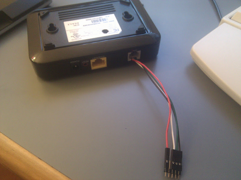
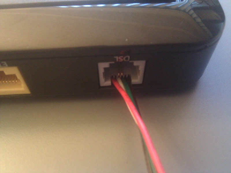
i'm trying to attach a serial port to my semi-bricked gt701d (it boots but do not get the dhcp daemon and other stuff up, actiontec says i can fix it with a restore program for windows that they send me but warned that a windows firewall or something would forever brick the modem... so instead of trusting windows network stack i will just have two openwrt devices in my network)

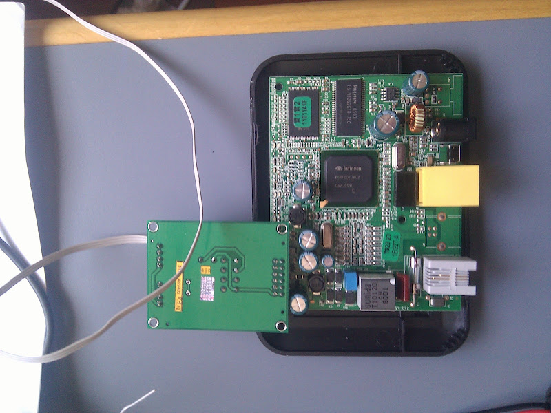
right now, on my first step, i'm already blocked for not understanding the wiki when it says: "Pin 1 is the closest to R441."

what's R441? resistor number 441? a chip that should have R441 labeled? i have neither sad


i've uploaded a pic of the board on the wiki. any help appreciated.

the picture has a terribly low resolution and differs totally from what's written there. anyway, it is mentioned, that pin 1 should be gnd. so you could measure the resistance of the first pin from each side against a common gnd source (like the shield of a connector or the gnd of the power supply connector) and whenever you get 0 ohms, you've got it.

Will put a better pic soon.

meanwhile, I did as you said, and it appears to be the pin closer the the "J5" printing the ground one. as it shorts with the ground shielding on the power supply input.

now, looking at the plugs for the rs232 line driver i have, the pins should be "+VCC,  RX0, TX0, RX1, TX1, GND"

so i tried to turn it on measuring the voltage DC on pin 1 and 6. and i get random mV readings at all times. nothing stable or near 3 or 5V i was expecting.

does that sound right?

tried to just plug it in there and attach to my box serial port on the other end, booting the modem with and wihout the reset button pressed resulted in absolutely nothing on the serial line...

some more bad pics taken with the phone camera:

the line board
https://lh6.googleusercontent.com/-Y-jdAQNRp5g/T6xlyA2hYTI/AAAAAAAAAd8/rUERaafMgjE/s800/IMG_20120510_180208.jpg

the setup
https://lh3.googleusercontent.com/-J8V_Jjg8CIg/T6xmE9V3eUI/AAAAAAAAAeE/3_xLJhwEJgk/s800/IMG_20120510_180141.jpg

hum... while upload the pics, tried to use port 1 instead of 0 on the line board... now i get something in my serial... garbage mostly. was using 9600 speed as i was expecting the modem to be in "damaged mode", but aparently it isnt'. changed to 38400, now i do have something!

here's the boot with the reset button pressed:

Basic POST completed...     Success.
Last reset cause: Hardware reset (Power-on reset)

PSPBoot3.3 rev: 3.3.7.15
(c) Copyright 2002-2008 Texas Instruments, Inc. All Rights Reserved.


Reset button pressed

(psbl) <cursor here>

here's the boot, mostly for my own documentation smile

(psbl) help
reboot            version           fa                printenv          
setenv            unsetenv          defragenv         fmt               
boot              oclk              help              
(psbl) boot
-----argv[0]=mtd1, argc=1

Booting...
Launching kernel decompressor.
Starting LZMA Uncompression Algorithm.
Copyright (C) 2003 Texas Instruments Incorporated; Copyright (C) 1999-2003 Igor Pavlov.
Compressed file is LZMA format.
Kernel decompressor was successful ... launching kernel.

LINUX started...
Config serial console: ttyS0,38400
Auto Detection OHIO chip
This SOC has MDIX cababilities on chip.
CPU revision is: 00018448
Primary instruction cache 16kb, linesize 16 bytes (4 ways)
Primary data cache 8kb, linesize 16 bytes (4 ways)
Number of TLB entries 16.
Linux version 2.4.17_mvl21-malta-mips_fp_le (yirun@localhost.localdomain) (gcc version 2.95.3 20010315 (release/MontaVista)) #1 Wed Aug 24 17:15:20 PDT 2011
Determined physical RAM map:
 memory: 14000000 @ 00000000 (reserved)
 memory: 00020000 @ 14000000 (ROM data)
 memory: 00fe0000 @ 14020000 (usable)
On node 0 totalpages: 4096
zone(0): 4096 pages.
zone(1): 0 pages.
zone(2): 0 pages.
Kernel command line: 
calculating r4koff... 00102c00(1059840)
CPU frequency 211.97 MHz
Calibrating delay loop... 211.35 BogoMIPS
Freeing Adam2 reserved memory [0x14001000,0x0001f000]
Memory: 14300k/16384k available (1564k kernel code, 2084k reserved, 103k data, 60k init)
Dentry-cache hash table entries: 2048 (order: 2, 16384 bytes)
Inode-cache hash table entries: 1024 (order: 1, 8192 bytes)
Mount-cache hash table entries: 512 (order: 0, 4096 bytes)
Buffer-cache hash table entries: 1024 (order: 0, 4096 bytes)
Page-cache hash table entries: 4096 (order: 2, 16384 bytes)
--------init push-----
Checking for 'wait' instruction...  unavailable.
POSIX conformance testing by UNIFIX
Linux NET4.0 for Linux 2.4
Based upon Swansea University Computer Society NET3.039
TI Optimizations: Allocating TI-Cached Memory Pool.
Using 384 Buffers for TI-Cached Memory Pool.
DEBUG: Using Hybrid Mode.
NSP Optimizations: Succesfully allocated TI-Cached Memory Pool.
Initializing RT netlink socket
Starting kswapd
Disabling the Out Of Memory Killer
devfs: v1.7 (20011216) Richard Gooch (rgooch@atnf.csiro.au)
devfs: boot_options: 0x1
pty: 32 Unix98 ptys configured
Serial driver version 5.05c (2001-07-08) with no serial options enabled
ttyS00 at 0xa8610e00 (irq = 15) is a 16550A
block: 64 slots per queue, batch=16
DEBUG: Initializing the voice port management module. 
DEBUG: Initialization of the voice port management module successful..
Error getting CPMAC Configuration params for instance:0
Environment Variable:MACCFG_A not set in bootloader
Setting Default configuration params for CPMAC instance:0
TI CPMAC Linux DDA version 1.8 - CPMAC DDC version 0.2
Cpmac: Installed 1 instances.
Cpmac driver is allocating buffer memory at init time.
PPP generic driver version 2.4.1
imq driver loaded.
avalanche flash device: 0x400000 at 0x10000000.
 Amd/Fujitsu Extended Query Table v1.1 at 0x0040
number of CFI chips: 1
Looking for mtd device :mtd0:
Found a mtd0 image (0xc0000), with size (0x300000).
Creating 1 MTD partitions on "Physically mapped flash:0":
0x000c0000-0x003c0000 : "mtd0"
Looking for mtd device :mtd1:
Found a mtd1 image (0x20000), with size (0xa0000).
Creating 1 MTD partitions on "Physically mapped flash:0":
0x00020000-0x000c0000 : "mtd1"
Looking for mtd device :mtd2:
Found a mtd2 image (0x0), with size (0x10000).
Creating 1 MTD partitions on "Physically mapped flash:0":
0x00000000-0x00010000 : "mtd2"
Looking for mtd device :mtd3:
Found a mtd3 image (0x10000), with size (0x10000).
Creating 1 MTD partitions on "Physically mapped flash:0":
0x00010000-0x00020000 : "mtd3"
Looking for mtd device :mtd4:
Found a mtd4 image (0x3f0000), with size (0x10000).
Creating 1 MTD partitions on "Physically mapped flash:0":
0x003f0000-0x00400000 : "mtd4"
Looking for mtd device :mtd5:
Found a mtd5 image (0x3c0000), with size (0x30000).
Creating 1 MTD partitions on "Physically mapped flash:0":
0x003c0000-0x003f0000 : "mtd5"
Looking for mtd device :mtd6:
NET4: Linux TCP/IP 1.0 for NET4.0
IP Protocols: ICMP, UDP, TCP, IGMP
IP: routing cache hash table of 512 buckets, 4Kbytes
TCP: Hash tables configured (established 1024 bind 1024)
Linux IP multicast router 0.06 plus PIM-SM
****ip_conntrack version 2.0 (128 buckets, 1024 max) - 380 bytes per conntrack
ip_tables: (c)2000 Netfilter core team
netfilter PSD loaded - (c) astaro AG
NET4: Unix domain sockets 1.0/SMP for Linux NET4.0.
NET4: Ethernet Bridge 008 for NET4.0
Initializing the WAN Bridge.
Please set the MAC Address for the WAN Bridge.
Set the Environment variable 'wan_br_mac'. 
MAC Address should be in the following format: xx.xx.xx.xx.xx.xx
VFS: Mounted root (squashfs filesystem) readonly.
Mounted devfs on /dev
Freeing unused kernel memory: 60k freed
serial console detected.  Disabling virtual terminals.
init started:  BusyBox v0.61.pre (2011.08.25-00:19+0000) multi-call binary
Algorithmics/MIPS FPU Emulator v1.5
/bin/cp  /etc/ppp/* /var/etc/ppp
cp: /etc/ppp/resolv.conf: No such file or directory
cp: /etc/dproxy.conf: No such file or directory
cp: /etc/dropbear: omitting directory
cp: /etc/gateways: No such file or directory
cp: /etc/hosts: No such file or directory
cp: /etc/init.d: omitting directory
cp: /etc/linux-igd: No such file or directory
cp: /etc/passwd: No such file or directory
cp: /etc/ppp: omitting directory
cp: /etc/resolv.conf: No such file or directory
cp: /etc/shadow: No such file or directory
cp: /etc/stunnel: omitting directory
cp: /etc/stunnel.conf: No such file or directory
cp: /etc/stunnel.pem: No such file or directory
cp: /etc/udhcpc: omitting directory
cp: /etc/udhcpd.conf: No such file or directory
cp: /etc/localhosts: No such file or directory
cp: /usr/www/html/pc_*.html: No such file or directory
cp: /usr/bin/add_dev: No such file or directory
 Reading Standard Configuration File /etc/led.conf

 Configured 51 states 
Using /lib/modules/2.4.17_mvl21-malta-mips_fp_le/kernel/drivers/atm/tiatm.o
registered device TI Avalanche SAR
Ohio250(7200/7100A2) detected
DSP binary filesize = 383830 bytes
tn7dsl_set_modulation : Setting mode to 0x1
Texas Instruments ATM driver: version:[7.00.01.00]
SIOCGIFFLAGS: No such device
mkdir: Cannot create directory `/var/run': File exists

Please press Enter to activate this console. ver new 3.0.4.1.4-GT701D,-2
ver old 3.0.4.1.2-GT701D,-2
ACS_Bootstrap= 1
dhcps ReservedAddresses=192.168.0.1
dhcps domain=domain_not_set.invalid
pPriv->ifaddr=
dhcps lease=86400
gcbwrt wrote:

Will put a better pic soon.

meanwhile, I did as you said, and it appears to be the pin closer the the "J5" printing the ground one. as it shorts with the ground shielding on the power supply input.

now, looking at the plugs for the rs232 line driver i have, the pins should be "+VCC,  RX0, TX0, RX1, TX1, GND"

so i tried to turn it on measuring the voltage DC on pin 1 and 6. and i get random mV readings at all times. nothing stable or near 3 or 5V i was expecting.

does that sound right?

apparently the pins mentioned in the wiki are more acurate then the lables on my rs232 line board smile

GND matches
TX1 and RX1 matches TX and RX on the modem
what my board says is TX0 is not used
what my board says is RX0 is +3.3V
what my board says is +VCC is unused

but it all works. somehow smile

A nice hack for the next one to need serial on this modem...

if you plug just the required 4 female jumper cables on the conectors (GND, TX, RX, skip, VDC, skip) and pass the cables trhu the hole in the adsl connector, you don't have to cut the case or open it to use the serial later.

https://lh5.googleusercontent.com/-2LzG8M9WG8I/T77wZ-yDsRI/AAAAAAAAAiI/htLkkPB4qzc/s800/IMG_20120524_193536.jpg

The cables are NOT being smashed. they go trhu perfectly. also the telephone cable plugs in without even touching the cables.
https://lh6.googleusercontent.com/-L-87KAr4YR0/T77wMF1rhaI/AAAAAAAAAiA/1dklUM8Cnwc/s800/IMG_20120524_193545.jpg

and i had the dremel all ready...

The discussion might have continued from here.