OpenWrt Forum Archive

Topic: TP-Link WR703N - Internal USB hub and flashdrive upgrade

The content of this topic has been archived on 6 May 2018. There are no obvious gaps in this topic, but there may still be some posts missing at the end.

Well i got my 703 awhile ago and its a great little box, even better once OpenWRT is loaded! I decided to pop mine open and see what was inside and i found there is quite a lot of space. This got me thinking about fitting a flashdrive inside, but I didn't want to loose the external usb. I decided a hub was needed!

After a bit of a search on ebay i decided to get one of these as the flying leads would be ideal to remove: http://www.ebay.co.uk/itm/190540919713
Turns out i was right, its perfect for hacking apart. You can also see my tiny 8gig flash drive which is only a fraction larger than a USB connector once the case is removed.

http://dl.dropbox.com/u/9511833/IMAG0352.jpg

I stripped the board and cut the boots off the USB sockets. These turned out to be ideal to reuse as well.

http://dl.dropbox.com/u/9511833/IMAG0354.jpg

The back of the hub PCB was bare apart from 1 crystal, so i decided to mount 2 sockets on it with double sided tape.

http://dl.dropbox.com/u/9511833/IMAG0355.jpg
http://dl.dropbox.com/u/9511833/IMAG0357.jpg

Keeping the wires as short as possible, i soldered them back to the connector on the other side.

http://dl.dropbox.com/u/9511833/IMAG0356.jpg

At this point i tacked the USB plug back on and tested it. Still worked!

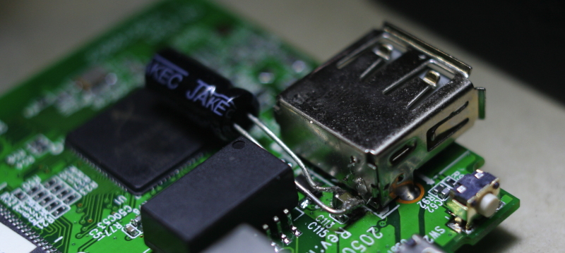
Next i removed the USB socket from the 703 board and soldered flying leads into place.

http://dl.dropbox.com/u/9511833/IMAG0358.jpg

Testing everything for size. I decided to use a 3rd USB socket from the hub, rather than the PCB mount one, for the external socket. This is fitted from the outside.

http://dl.dropbox.com/u/9511833/IMAG0359.jpg

Flying leads from the 703 USB trimmed and soldered back to the hub. External socket wired in.

http://dl.dropbox.com/u/9511833/IMAG0360.jpg

I covered the back of the hub PCB with insulating tape and used a hot glue gun to fix the USB socket to the case. Popped the hub in and got the wires nice and tidy with a pair of tweezers.

http://dl.dropbox.com/u/9511833/IMAG0361.jpg

All tested and worked first time! To get the lid back on i had to cut the 2 plastic pillars off it. The 8Gb flash drive is set up with a 512Mb swap partition and the rest of it EXT3.

Im really pleased how this has gone together, let me know what you think!

(Last edited by JamesA on 19 Jan 2012, 15:44)

Wow super cool smile i just got mine with the mail. I think i need to order a hub soon is handy that you can wire your own ports.

Glad you like it smile

As long as you have a good soldering iron and a steady hand its not too tricky. Desoldering the USB socket was probably the most risky part as one of the holes just wouldnt clear with my solder sucker. Thought i was going to overheat it and start lifting tracks, seems to have survived though!

(Last edited by JamesA on 23 Apr 2012, 09:07)

Hi James, nice writeup and idea-

1 - you've tested the new setup with more than 1 USB drive?
2 - how much current consumption (from 5V microUSB) does your hub add to base, in idle ? compared to normal USB?
3 - any temperature considerations adding inside the box?

Hi Jim, thanks and glad you like it.

Yes I've had it running with a 2nd 8Gb USB drive plugged in as well. Worked fine. I also tested a USB hard drive which also worked fine as it had its own power supply.

Not tested the power draw, bit I cant imagine its going to be a lot. I do want to put together a small battery pack to run it as well so that should give a good idea of consumption.

Had it on test on my desk at work all day yesterday and its was warm but stable. I popped the lid off towards the end of the day and the hub was quite warm. I need to get the glue gun out and stick the sockets on better as the double sided tape doesn't cut it. I'm also going to replace the tape on the bottom with a small piece of that fibreglass insulation sheet stuff, like you find in mains transformers. Just need to track some down, I opened up 2 old UPS's today and didn't find any hmm

Great!

On the mainboard just to the right of the vertical 4 contacts for the original USB port - there are 2 holes. Were these originally used to anchor the original USB port (via solder?)?  If so, maybe minimally cut the 4 connectors under the original USB port and leave that one in place, solder the HUB to this, then resolder one of the HUBs output to the USB port's pins? (I think you were building along the way with your example and seeing if itd work well)

Just an idea if others are using your guide as a template. Looks like plenty of space to bring an extra connector or two of those HUB's 4 thru the case, just melting through the plastic.

'Waiting on mine to arrive from CN,

(Last edited by jimbeans on 21 Jan 2012, 01:35)

Yes thats exactly what those holes are. You could probably do something like that with the USB, its what i was thinking originally. You would need to remove the socket still as there is no access to the connectors from the back of the socket. Perhaps replace it with a different PCB mount socket or cut the case open once its removed. Mine went in the bin as i pulled one of the wires out while i was removing it hmm

(Last edited by JamesA on 21 Jan 2012, 02:40)

Very nice hack!

Isn't the flash still too hot ? I've seen these going quite toasty..

BTW guys, speaking of USB, I managed to improve the compatibility with "bigger" devices by adding a 100uF on the USB rail itself. I had a webcam that wouldn't work before, and worked afterward, I suspect some devices make the 5V "dip" too much at startup.

It's not very pretty, but it easily doable, and works:
http://oomz.net/p/web/IMG_5862.JPG

nice mod,
I planning to do the same with my wr703n

i ordered this www.ebay.com/itm/260925684076 and hope it works properly like in this thread.

which USB-storage have u used?

if i dismantle the cable www.ebay.com/itm/290654220055 and solder it to ground and antenna pcb pads,  it should be able to add an extra external antenna to it?

there is only one internal antenna?

What about writng a howto for this device using extroot?

(Last edited by cave on 3 Feb 2012, 12:42)

Thanks Buze, that's a nice addition you have done there too! I'll have a look through my junk box for a suitable cap and add it myself. What webcam to you use? I'm looking for a cheap one to hook up myself. It does get a warm, but I've had it running for 4 days solid and it was stable so quite happy with that.

Glad you like it Cave, I'm sure you will be fine if you are careful with your soldering iron. You will have to see how it goes with that hub, hard to tell the size until you have it to hand. The hub i used was the 2nd one I ordered, the 1st was too big to fit inside. Let us know how you get on smile

I've now used my hot glue gun to fix the sockets onto the PCB and I've replaced the tape with a piece of 0.5mm PTFE sheet cut to size. Much better all round.

The USB stick is the 8gb one of these: http://tinyurl.com/89tlnd5
Id had it awhile and the plastic was cracked so I removed it. Turned out its actually a microSD card in reader so I replaced the card with a faster class 8 card I had spare. I'm planning to get a Sandisk Cruzer Fit sometime to see what they perform like as they are tiny too.

Currently im using firmware build by Twinclouds that includes USB, tools and LUCI which works really well. Try dropping him a PM and see if he will share if you are interested. I used his instructions, which were taken from the wiki to get EXTROOT working. Should work fine on vanilla firmware as long as you have USB etc installed already.

Twinclouds wrote:

1. Format then mount the USB drive (I mount to /mnt/sda1 so I can copy the copy statement directly, but you can mount it to anywhere).
2. Modify the /etc/config/fstab.  The relevant sections are as follows:
config mount
        option is_rootfs 1
        option target   /overlay
        option device   /dev/sda1
        option fstype   ext4
        option options  rw,sync
        option enabled  1
        option enabled_fsck 0

config swap
        option device   /dev/sda2
        option enabled  1

Note that I formated sda1 to ext4.  To wear and tear, I disabled its journal function.  In addition, I used /dev/sda2 as swap partition.  It may not be necessary.  To make sure swap is always turned on, I added "swapon /dev/sda2" in /etc/rc.local

3. Copy the overlay content to the USB by:
tar -C /overlay -cvf - . | tar -C /mnt/sda1 -xf -
4. Reboot 703n.  Do a df to see if rootfs and overlay have a lot of memory space now.
That's it.  Good luck

I tweaked this a bit to make sda1 512mb swap, sda2 4gb root and sda3 3.5gb spare for storing scripts or anything else i didnt want to loose if i reformat the root.

cave wrote:

if i dismantle the cable www.ebay.com/itm/290654220055 and solder it to ground and antenna pcb pads,  it should be able to add an extra external antenna to it?

there is only one internal antenna?

S7mx1 posted some pics and a link to a thread about adding an external aerial: https://forum.openwrt.org/viewtopic.php … 57#p152457
Im not sure if both the hub and the aerial connector would fit. You could have it on a flying lead. Have to suck it and see.

(Last edited by JamesA on 3 Feb 2012, 13:05)

very nice modd.  thanks for sharing ...

hi jamesA

first off all , thanks for this fabulous mod !

i did all the stuf , i used a 8go usb drive for me swap is on sda 1, sda 2(ext3 overlay and sda 3(ext3) MyData.
When i try to copy th e overlay , nothing happened. principal overlay is empty...

(Last edited by patmtp35 on 23 Feb 2012, 14:29)

@patmtp35: Please provide a console log of what you tried.

ok i ll try

(Last edited by patmtp35 on 23 Feb 2012, 22:55)

Help please. I tried to install the firmware.
Now I can not enter the address 192.168.1.1
How do I restore the old firmware

What is the address needed to enter the--Emergency Web Server

You would probably get more help if you start a thread in the general section and give some more details about what you have done and what you are trying to do.

However, check the wiki for details on recovery boot and reverting to stock firmware. If that doesn't help, start a new topic in general.

great!!! I was looking for this. Thank you very much!

peace

I plugged a flash memory stick into the stock port on my 703N, but I'm having difficulty mounting it.

Log file shows:

May  4 20:54:54 OpenWrt kern.info kernel: [ 9349.850000] usb 1-1: new high-speed USB device number 4 using ath79-ehci

When I plug it in.  I see /dev/1-1 and /dev/usb1 but I get errors when I try to mount or fdisk them:

root@OpenWrt:/dev# mount /dev/usb1 /mnt
mount: mounting /dev/usb1 on /mnt failed: Block device required
root@OpenWrt:/dev# mount /dev/1-1 /mnt
mount: mounting /dev/1-1 on /mnt failed: Block device required
root@OpenWrt:/dev#

and:

fdisk: unable to read /dev/usb1: Operation not permitted
fdisk: unable to read /dev/1-1: Operation not permitted

My /dev list looks like this:

root@OpenWrt:/dev# ls
1-1        mtd1       mtd5       null       ttyATH0    ttyS15     ttyS9
console    mtd1ro     mtd5ro     port       ttyS0      ttyS2      urandom
full       mtd2       mtdblock0  ppp        ttyS1      ttyS3      usb1
kmsg       mtd2ro     mtdblock1  ptmx       ttyS10     ttyS4      watchdog
log        mtd3       mtdblock2  pts        ttyS11     ttyS5      zero
mem        mtd3ro     mtdblock3  random     ttyS12     ttyS6
mtd0       mtd4       mtdblock4  shm        ttyS13     ttyS7
mtd0ro     mtd4ro     mtdblock5  tty        ttyS14     ttyS8


What should I be doing differently?

Thanks in advance.

Nevermind, I figured it out.  I had to install kmod-usb-storage.

Hi,
Im trying to configurate that router for use a usb memory to install the programs (luci, etc) but i can't do it...
anyone can explain how to configurate the router for that.

thanks (i read a lot of documents on internet but no one run (or almost with that router))

Hi,

I'm looking at doing a similar mod but with the powered 7-port version of these "octopus" hubs so I can use more peripherals. I've noticed that if the 307N is powered via micro usb and then a powered hub is installed via the normal usb port, the micro usb cable can be removed and power will still be provided (i.e. the 307N stays up by switching to drawing its power from the hub). However, if only the powered hub is connected when the 307N is switched then it won't boot. So it seems the router can draw power from the normal usb port but it won't boot in this configuration.

A solution is to simply connect one of the hub's 7 ports to the 307N's micro usb, but it would be cleaner if I could hack the board to allow the hub to power it via the normal usb port from scratch. Does anyone know whether this might be possible and have any suggestions I could look into?

most likely you have sorted your problem, mcarthb, but you can take power and gnd from the hub (most likely a couple of big pads with lots of connections already attached).
As the data lines on the microUSB are n/c, you just need to wire the power to the relevant pins (might as well get rid of the socket, replace it with a bayonet socket (or something else of your choice) and attach the serial pads to it for easy access.

The discussion might have continued from here.