Before flashing mine, I tried that but without success. The only way I was able to unlock my bootloader was using a SPI flasher.
You need to see in your flasher which pin is the 3.3v, they should be labeled. Then look at the router's board and identify the UART 4 pins, one of them says 3.3v (it's the one you DON'T use when accessing the console).
Refer to the following picture I took when I flashed mine:

As what happened to Roger, I also needed to connect those 2 pins along with placing the clamp that comes with the flasher on the chip, or else the flasher wouldn't detect the chip. To perform that connection I used a a dupont jumper wire (female to female), which I had to buy separately, but these are also dirt cheap - this along with the male pins that also came with the flasher and that I placed on the board's UART pin holes (didn't need to solder them, as long as they made contact).
Side note: my flasher also has a TTL UART mode, there is a jumper connector in it so I can alternate between TTL UART mode and SPI flashing mode (so I don't need a separate TTL UART adapter to access the router's console). Yours probably will have the same feature, if so then make sure you are in the correct mode for what you are doing.
1 Like
Thanks for fast reply.
I now feel alot more sure of all the steps
/Henrik
Hi.
No, mine has a 3.3V pin, see below in this picture:
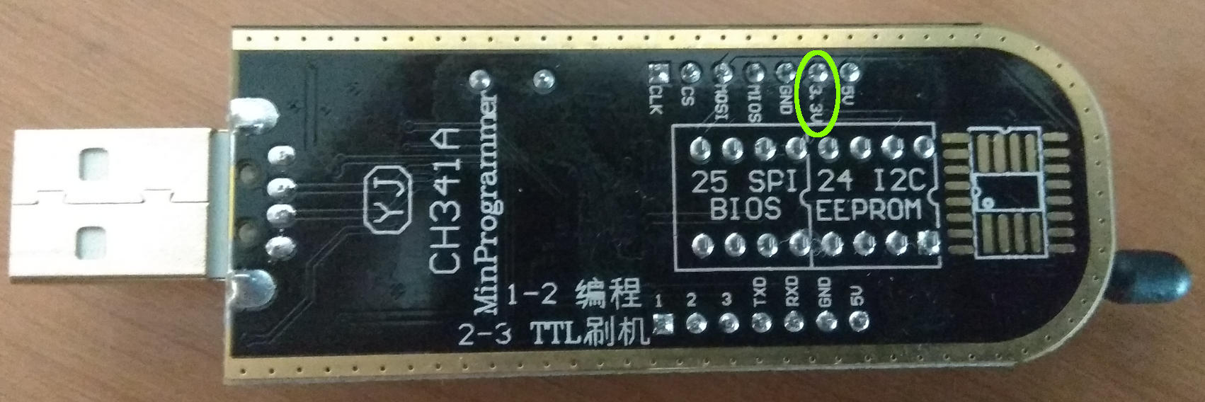
I think that the pins in the top row in this image are only usable when in flasher mode, but I could be wrong.
Anyway, this marked pin is the one I connected to the router's TTL UART 3.3V pin. Note that when I connected the clamp to the adapter (via the interface that is on the other side), the pin got covered by it so I had to twist it gently to be able to connect the dupont cable (this is noticeable on the picture that I put on my previous post). This may be the case with your adapter or not, but don't find it strange if it's the same with you (just don't twist it too much so you don't break it).
Also, you may try to connect the flasher without connecting the 3.3V and see if it works for you, but for me (and Roger above), without doing it, ch341prog wouldn't detect the chip. Do a ch341prog -i and it will be obvious if things are ready to go.
I know for sure the following, about the bottom row:
- pins 1,2 and 3 are used to select the mode: short 1-2 for flasher mode, short 2-3 for TTL UART adapter mode (it comes with the jumper connector on the other side for doing that)
- the other 4 pins (TXD, RXD, GND, 5V) are for using when in TTL UART mode
Reminders (in case any doubts subsist):
- When flashing you do NOT connect the power supply to the router, only the clamp on the chip and the aforementioned 3.3v pin.
- However when accessing the router console, in TTL UART mode (baud rate 115200) you need to have the router powered on with it's power supply, and you MUST NOT connect anything to the board's 3.3V pin (or else you may fry the board, the adapter, or both). You should JUST connect:
- RX pin from the adapter to the TX pin on the board
- TX pin from the adapter to the RX pin on the board
- GND pin from the adapter to the GND pin on the board
- I heartily recommend that you don't forget to make a backup of the flasher's dump before modifying and flashing it back, should you want to revert things if something's not working.
Hope this helps.
That does not mean that this adapter is designed for 3.3V operation! CH341A chip itself is powered from 5V USB directly, so the voltage on its logical outputs will be around 5V as well. This adapter requires modification to work with 3.3V chips.
For CH341A software i use AsProgrammer_1.4.0
1 Like
Well, I confess that I didn't measure the voltage and just trusted the label... But it worked, could it have been luck?
Well, I picked up my multimeter and checked. The 3.3v pin on my flasher indeed is 3.3v, when measured against the GND pin, and the 5v is 5v as it should. Hope it helps.
you don't understand the problem
I'm talking about the logical outputs of the chip - measure the voltage there, or just find the circuit diagram and check there.
Sorry, I really don't understand. Maybe someone with better knowledge about electronics can help further.
schematic :
i use a long time without problem ( only the little regulator a little hot for use with my motherboard MSI-GAMING-5 , i just stuck a little piece of metal on the AMS1117 3.3 )
1 Like
My SPI programmer arrived and I've got my R2Gv2 flashed and running Openwrt. I can confirm both device are identical and work perfectly.
I didn't need to connect a 3.3v cable to it, the usb 3.0 on my PC supplied enough power.
Read the whole flash, saved a copy, changed the bootloader stop/wait time with the hex editor the flasher program has built-in and flashed the changes on the fly so to say.
Thx to @rogerpueyo for his initial porting work.
2 Likes
Hi guys.
Lately I've been having some issues with the router losing 2.4GHz wifi. For a while (while I was out on vacation) I left it rebooting every 2 days via crontab, but now that I've disabled that the problem reappeared.
Please note that I have an IP camera that is constantly connected and sending traffic, that could probably make it easier to trigger the problem. However I must say that I have another mt76 based openwrt device (mt7628 SoC) that is connected to another IP camera (same model and brand) and that one never fails (at least since about almost year ago the mt76 driver got stable), so the problem looks to be localized to this router.
Seems to me to be an issue with the mt76 driver so I opened an issue there:
Anyone else having this problem? Or any other suspicion, looking at the log I posted there?
Thanks in advance.
1 Like
No problems at all on my R3Gv2 but I've only had it up and running a few days.
I'm no expert but comparing the R4AG and R3Gv2 port patches there are a few discrepancies when there shouldn't if they are clones.
I pulled the R3Gv2 port patch into my local repo and made a few changes to it taken from the R3Gv1 as they are almost identical also.
Thanks for the suggestion. Unfortunately I have some specific packages on my build, so I didn't use yours. Instead I also pulled some of the changes from the 3Gv2 patch into my build, more specifically, some parameters on the DTS file.
I didn't touch the "ralink,group" on the pinctrl section because it didn't seem relevant (and anyway I don't really know what that part is for and the meaning of the different parameters), but changed some addresses and the SPI frequency.
Let's see how this goes. Already flashed my device with this new build and looking good so far, but too soon to see if it's more stable.
Should anyone be curious, here's a patch (to apply from openwrt/master lastest commit) with the changes I made to try merging Roger's patch and the 3Gv2 currently proposed patch:
If it looks good, @rogerpueyo you can use this in your repo  Also, can you make a pull request for integrating the support on the official openwrt tree?
1 Like
Any update on the problem, was it solved with your patch?
Hi.
So far, so good, with uptime of about 2 days. For now just one minor hiccup on the IP camera connection to the NVR, of a few seconds (meanwhile I've also configured NVR to send emails when that happens, which gives me additional precision to detect failures), but no error messages on the kernel ring buffer of the router.
But I think I'll wait some more time until considering it a full success. I'll be happy when the uptime is of a few weeks with no video losses, like with the other camera on the other side of the house which is connected to other (mt7628) weaker AP
1 Like
6 days of uptime and no kernel messages indicating errors. In terms of WiFi stability, not 100% but about 95% - still have some breaks now and then, of some seconds, but way less. Meanwhile I've also fine tuned some parameters (e.g. disabled short gi to try to improve communications across a wall), but that's more related to my environment that anything else.
So in my experience, the patch I referred has been performing better. Should anyone have issues, feel free to try it.
Thanks @Gingernut for the tip.
1 Like
Hello my spi/uart usb Interface arrived. Opend the router it did not looked the pics (no SPI chip). With the uart connected i noticed that i dont have a R4A I have an R4 and from what I can read its a nand device.
I got access to CLI and uart. It had the 5 sec bootdelay from factory so problem accessing the CLI to enable uart.
I know this might be a bit of topic but how to compile the firmware for the R4, is it possible ? Can I use same image ?
/Henrik