Thanks for your tips. I tried to install hostpad and then the wifi connection work now.
1 Like
Hello Guys,
I've just registered to thank you with all your job.
I've found this cheap AP on chinese MI store without knowing nothing at all about compatibility.
With your informations I figured out how to flash the firmware, so I compiled it.
Wifi seems pretty fast but I'll check it better as soon as I can, the link speed seems to be beetwen 650-800Mbps.
I want to share my personal version of the fw, maybe could be helpful for someone. 
What is included:
Luci https interface with classic and material theme (English and Italian interface)
OpenVPN Client
MJPEG server (useless)
QoS
DDNS
Statistics Graphs
AdBlock and Simple AdBlock
Notes:
Luci is very slow with chrome, use firefox instead.
The classic theme is not allowing to modify the wifi parameters, use material theme instead.
Hope it helps.
Enjoy!
Hi guys, what I am doing wrong?
added the 4 pin header and used a fdti ft232rl 1232-c but i get no output in putty. The comm port is correct. if I swap Rx and TX I get junk appear in putty
I flashed a D1 mini nodeMCU as USB to TTL debuger as here https://www.cnx-software.com/2017/04/07/transform-your-esp8266-board-into-a-usb-to-serial-board-easily-with-arduino-serial-bypass-sketch/
but the same happen. With RX and TX the correct way round all I get is a blank screen in putty however if I reverse RX and TX then I get junky output in putty.
Tried a second computer and teraterm just in case.
Any idea? Baud rate maybe, at present it is 9600?
example of the output from putty when I reverse the TX and RX
▒Т;▒▒;;#▒
         ▒#7#▒▒▒3▒"3*";6#'▒▒"▒""2▒▒▒▒▒▒▒▒▒▒▒▒▒▒▒▒▒▒▒▒▒▒▒▒▒▒▒▒▒▒▒▒▒▒▒▒▒▒▒▒▒▒▒▒▒▒▒▒▒▒▒▒▒▒▒▒▒▒▒▒▒▒▒▒▒▒▒▒▒▒▒▒▒▒▒▒▒▒▒▒▒▒▒▒▒▒▒▒▒▒▒▒▒▒▒▒▒▒▒▒▒▒▒▒▒▒▒▒▒▒▒▒▒▒▒▒▒▒▒▒▒▒▒▒▒▒▒▒▒▒▒▒▒▒▒▒▒▒▒▒▒▒▒▒▒▒▒▒▒▒▒▒▒▒▒▒▒▒▒▒▒▒▒▒▒▒▒▒▒▒▒▒▒▒▒▒▒▒▒▒▒▒▒▒▒▒▒▒▒▒▒▒▒▒▒▒▒▒▒▒▒▒▒▒▒▒▒▒▒▒▒▒▒▒▒▒▒▒▒▒▒▒▒▒▒▒▒▒▒▒▒▒▒▒▒▒▒▒▒▒▒▒▒▒▒▒▒▒▒▒▒▒▒▒▒▒▒▒▒▒▒▒▒▒▒▒▒▒▒▒▒▒▒▒▒▒▒▒▒▒▒▒▒▒▒▒▒▒▒▒▒▒▒▒▒▒▒▒▒▒▒▒▒▒▒▒▒▒▒▒▒▒▒▒▒▒▒▒▒R▒▒▒▒▒▒▒▒▒▒▒▒▒▒▒▒▒▒▒▒▒▒▒▒▒▒▒▒▒▒▒▒▒▒▒▒▒▒▒▒▒▒▒▒▒▒▒▒▒▒▒▒▒▒▒▒▒▒▒▒▒▒▒▒▒▒▒▒▒▒▒▒▒▒▒▒▒▒▒▒▒▒▒▒▒▒▒▒▒▒▒▒▒▒▒▒▒▒▒▒▒▒▒▒▒▒▒▒▒▒▒▒▒▒▒▒▒▒▒▒▒▒▒▒▒▒▒▒▒▒▒▒▒▒▒▒▒▒▒▒▒▒▒▒▒▒▒▒▒▒R▒▒▒▒▒▒▒▒▒▒▒▒▒▒▒▒&.▒▒▒▒▒▒▒▒▒▒▒▒▒▒▒j7#+▒▒▒▒▒"3*f
                         ▒:&▒7▒*:***▒::▒***:**▒▒"32:&:▒▒▒3▒"▒▒▒#""r+"▒"▒;▒>▒▒▒▒▒▒W▒R▒▒▒▒W▒�_▒b▒_▒Gf�▒/W▒b7
 bwk
    ▒rgg▒k▒▒kGc▒G▒K▒^▒nf▒▒▒▒kWkWã▒&▒wʋ▒▒▒Z▒ZW▒▒▒f.fKZZ▒▒Bg▒~Sk▒kSZC▒RV▒i▒N▒oZ▒▒▒Q▒▒▒▒GRo▒▒PR▒
                                                                                             ▒_▒nk▒s▒oWZ▒#▒▒▒▒Zc▒Zg▒R▒oK"fkcW▒Z▒▒wZ▒▒g▒oo▒vsZ_▒Z/'Z▒▒w▒F▒W▒▒F▒▒Ɨ▒w▒▒▒G▒Rw▒F▒G▒▒grZ▒▒Fw▒▒CGV▒▒w▒F▒W▒▒GVo▒▒▒Z▒kSZo▒Z▒k▒▒▒ZbR▒▒o▒n^�So^R▒▒▒▒▒JRg^▒^[▒R^▒R▒{▒^#▒▒^7c▒[w▒^7▒^▒
                                                       3▒SK▒▒^▒▒R^3S▒s^▒wZ▒▒
                                                                            RғwSӷZ▒▒Z▒^▒R▒▒▒R▒Z▒wS▒▒R▒▒ZWZS▒cGGZZbW*W▒W6▒▒W6▒66_▒_6_cSW6WXWW▒WV▒VX▒8X_X_6▒V▒WRWbZ6▒6W6▒W6▒6_6▒▒_6߆▒▒WR▒b^W^▒▒^WV▒6:▒V6▒Z▒▒Vc▒▒▒c▒bcbsccG▒Z▒k▒gқZ▒n▒▒S▒▒KZ▒oB▒r▒2B
                               rwVVwDVZ▒JVZ▒#ZGVG▒VZ▒▒cKoӐW▒k▒▒RV
                                                                 ▒Z▒RjҜZ▒R▒Z▒f▒▒ZnRV▒cZ3Z▒ZZ▒▒▒▒▒Z▒VZ3▒G▒Z▒BR▒▒k▒▒▒Z▒▒J▒c▒▒rZ▒Z▒g▒2Z▒2gZ▒"▒▒G▒▒co▒▒oc[▒Rco▒oZ▒▒B▒kF▒▒k{▒h▒#ZV▒kc▒Kcߑ▒_cocc▒▒g▒F^▒▒▒
                                                                                          ▒g▒▒[
                                                                                               ▒w▒▒g▒*^^▒^▒▒^▒k▒^k▒^w▒^▒R^▒^�r▒Z▒ZZ
                          ▒Z▒2Z▒▒▒ZGS▒▒▒ZZ▒▒S▒Z▒k▒▒Kי▒▒^Gw▒kGw▒▒▒wg▒^▒▒O▒Z▒b▒b▒c▒▒Z▒▒^3{▒▒_▒^▒'▒S▒▒^▒▒[^▒'k▒▒^^▒Z▒▒Z▒▒Z2▒▒▒gZ▒Zh▒▒▒RZ▒▒▒Z▒▒▒▒▒▒SSO▒S▒ώ▒S▒▒ӐO▒SC▒S▒O▒SOnSS▒S▒▒▒▒ƑS▒▒ӐC▒▒▒▒nS▒▒^▒▒▒S▒C▒S▒▒▒S▒▒▒▒▒jS▒▒▒S▒▒SO▒S▒▒
Your adapter RX must be the board's TX, and your adapter TX must be the board's RX, that's why you only see output that way - that is the correct way.
Baud rate that worked for me was 115200. Can you try that?
1 Like
hahaha, I just figured out exactly what you said then come back to post my success and saw your answer.
baud 115200
that was scare got to u-boot and did setenv uart, telenet,SSH and then reboot and it kernal paniced everytime
In the end I used option 1 and uploaded image from TFTP.
This is certainly not for the faint of heart
guessing to update keneral in open wrt I have to compile my own build and flash from open WRT.
Ordered a Xiaomi Router 3G and received the new v2  , model R3GV2 with no usb port, 16MB SPI flash and 128MB RAM, seems identical to the 4A so I thought I'd post it here.
Cracked it open, captured a bootlog and took a pic.
That flash chip sure looks like to be similar, if not the same, as the 4a gigabit edition. Do you have a flasher? If not, they're pretty cheap (mine cost about €3.5 on that big chinese supermarket everyone knows, took about 3 weeks to arrive to Europe). Once you dump the contents of the flash and keep a copy of the original, it's just a matter of experimenting with minimal risks, I'd say...
1 Like
I'll be ordering one ASAP.
Thanks to the folks that took the time to investigate and get OpenWRT supported.
1 Like
Hi!
As motherboard model, 99% you got the A4 Gigabit Ed.
If you can get the SPI Programmer and modify the bootdelay, you can flash the build that I linked few days ago, or build your own!
1 Like
Ordered one last night and it has been posted today. Should arrive in a few weeks.
I'll keep an eye on the thread in the meantime.
Thxs
Someone posted a patch to support the R3G v2 to the OpenWrt mailing list, this might be of interest if indeed the R4A Gigabit is identical.
I'm in no way a go between for the author, so any questions should be directed directly to him.
1 Like
Hello i just ordered the SPIflasher and uart adapter. I was reading about the extra 3.3 v connection, how to connect ?
Looking forward to use wrt in the R4
/Henrik
In this patch : https://patchwork.ozlabs.org/patch/1095406/ , for a different router (4A but 100Mb variant) there are instructions referring about cutting power on a specific erase action. Can anyone try this method on this router, it may work without the need for the programmer.
INSTALLATION:
- Connect to the serial port of the router and power it up.
If you get a prompt asking for boot-mode, go to step 3. - Unplug the router after
> Erasing SPI Flash...
> raspi_erase: offs:20000 len:10000
occurs on the serial port. Plug the router back in. - At the prompt select option 2 (Load system code then
write to Flash via TFTP.) - Enter 192.168.1.1 as the device IP and 192.168.1.2 as the
Server-IP. - Connect your computer to LAN1 and assign it as 192.168.1.2/24.
- Rename the sysupgrade image to test.bin and serve it via TFTP.
- Enter test.bin on the serial console and press enter.
Before flashing mine, I tried that but without success. The only way I was able to unlock my bootloader was using a SPI flasher.
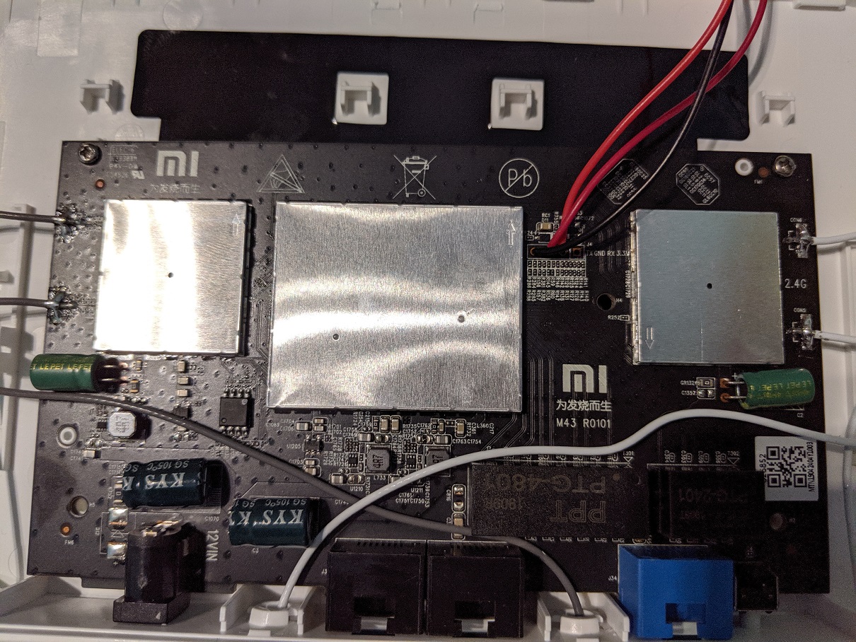
You need to see in your flasher which pin is the 3.3v, they should be labeled. Then look at the router's board and identify the UART 4 pins, one of them says 3.3v (it's the one you DON'T use when accessing the console).
Refer to the following picture I took when I flashed mine:

As what happened to Roger, I also needed to connect those 2 pins along with placing the clamp that comes with the flasher on the chip, or else the flasher wouldn't detect the chip. To perform that connection I used a a dupont jumper wire (female to female), which I had to buy separately, but these are also dirt cheap - this along with the male pins that also came with the flasher and that I placed on the board's UART pin holes (didn't need to solder them, as long as they made contact).
Side note: my flasher also has a TTL UART mode, there is a jumper connector in it so I can alternate between TTL UART mode and SPI flashing mode (so I don't need a separate TTL UART adapter to access the router's console). Yours probably will have the same feature, if so then make sure you are in the correct mode for what you are doing.
1 Like
Thanks for fast reply.
I now feel alot more sure of all the steps
/Henrik