Note that excessive heat form soldering could damage some components if you are not careful. don't keep soldering and re-soldering (I see indent marks on the board from the solderer, so be careful, never let the solderer touch the board, certainly anywhere other than the soldering points, and also not for longer than necessary.
Baud rate seems to be the usual, though I'm not sure if it's also that for this particular device. It wouldn't harm to try other baud rates.
I don't know if you have to to bridge points, but I wouldn't try anything like that until I'm 100% sure.
Check with the guys in this topic Bricked TL-WA850RE v2 to see if any of them faced a similar problem if they go t to that point.
I guess you know you have to plug in the repeater, it's the reason why you do not have to connect the positive pin of the adapter, otherwise it does not work.
Welcome @exp10r. There should be release 18.06.02 for TL-WA850RE v2.
I'm not sure what your question exactly is, but as it does't seem very related to the subject of the original post, you should make a new topic if you have more questions.
indeed, the question is not related to the topic. but little those on topic TL-WA850RE v2 . Looking for sources Lede 17* which have support for TL-WA850RE v2.
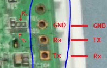
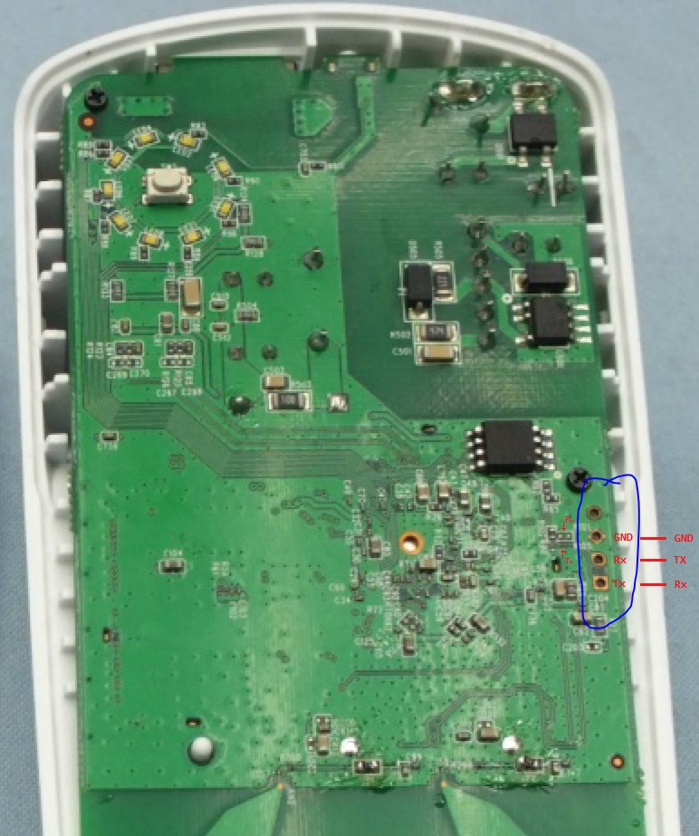
I have the same device, bricked it for almost the same reason, the section where you should use a .bin image from OEM based on whether it has 'boot' or not is wrong, I didn't have the 'boot' in the image and therefore should've no problem flashing the original firmware back, I had the same problem with sysupgrade, it didn't work, so I used the mtd method, which bricked the device since it loops the same sequence with the LED's flashing, I also tried TFTP methods based on hardware similarities with older routers and failed.. I then bought a USB TTL device and used telephone wires for the connection.. a multimeter was used to check UART TX,RX,GND,VCC, and I'm not so sure it's the same as in the picture, from left to right, the first two have voltage of about 2.7 each the others don't, using a continuity test the 3rd was the only one to beep with other components in the circuit board and I deemed it to be GND, so if I checked it right the image holds up, yet after connecting GND, TX, RX and flipping both TX and RX, fired up 'screen /dev/ttyUSB0 and started to wait for something to show up (shorting the wires intentionally proved the TTY was working since it printed some characters), connected the device to its power adapter and nothing... after a few tries I thought maybe its something with the ground, shifting the ground cable caused a blackout... I have NO IDEA as to why there's no response... but it's very similar to this.
a few notes about the pictures:
I used analog voltage, I later switched to DC and got 2.7V.
Telephone wires are securing the device to the USB TTL
PREP work (Multimeter etc..):
Actual connection:
So I'm stuck and I'm right there with you @tplinkuser2
I don't like that telephone wire arrangement at all you should get three actual square pins and either solder them in or push them in the holes and tilt to the side so they make contact. The other end of the pins would go in the female sockets of your jumper wires.
Have you set the baud rate? I use picocom instead of screen it lets you set the baud rate in the same command line.
The only issue I see is the original OpenWrt image size too big to be flashed as it is.
I had to make an image with the following command using the Image Builder: make -j4 image PROFILE=tl-wa850re-v2 PACKAGES="-luci-proto-ppp -ppp -ppp-mod-pppoe -kmod-ppp -kmod-pppoe -kmod-pppox -opkg"
And use the openwrt-18.06.5-ar71xx-tiny-tl-wa850re-v2-squashfs-sysupgrade.bin to flash as already explained. Must work.
Important: now the device will be running OpenWrt without web interface. It's impossible to add Luci and required files to run web interface considering the small memory size WA850RE has.
I have been able to restore it , but with firmware openwrt 18.06.5 sysupgrade. I think that with stock firmware is also restorable. NOTE: I can't save the config settings with openwrt, erase all turning off the device.
You have to bridge 2 points (try it first with Tx and test it, after Rx). Note: you'll need usb to rs232 ttl converter module, pins working at 3.3V (TTL level voltage).
Setting ip pc to 192.168.1.10, run tftp server (tftpd32) on ethernet interface, download lastest firmware openwrt 18.06.5 sysupgrade version, rename to firm.bin (for easy use). Note: data (firmware) is sent on ethernet interface, commands are sent on serial interface UART. Note:openwrt 18.06.5 sysupgrade
md5: 9464728d3dbfe7a232766811e19db5d4
sha1: 2f7732e64088de06f19ddbcfc5ac2def6d4d12c8
sha256: 8b80f93c2c58ed01b487c55241d233ac4f57209a1996ccb67a386b2aa08d65e4
Setting baud rate to 115200 (PuTTY console), no flow control. Note: I have stopped loop with typing tpl.
In my case setting to 128000 can see characters but not stop loop.I have stopped loop, setting baud rate to 115200 and only connecting Rx on device (repeater). Because if connect Tx too, i can see rare characters, and cant use ctrl-v, which interfere with ctrl-v.
Conclusion I did it without seeing.
During "Autobooting in 1 seconds" type tpl. Note: open notepad, typing tpl, select it all, copy for use it into console (PuTTY) with click right or ctrl-v.
set where to find for file firm.bin
copy firm.bin from tftp to ram memory (0x80060000 address).
erase 0x380004 (3670020 Bytes) from flash memory (starting at 0x9f020000).
copy firm.bin stored in ram to flash memory (0x380004 Bytes).


 , but with firmware openwrt 18.06.5 sysupgrade. I think that with stock firmware is also restorable.