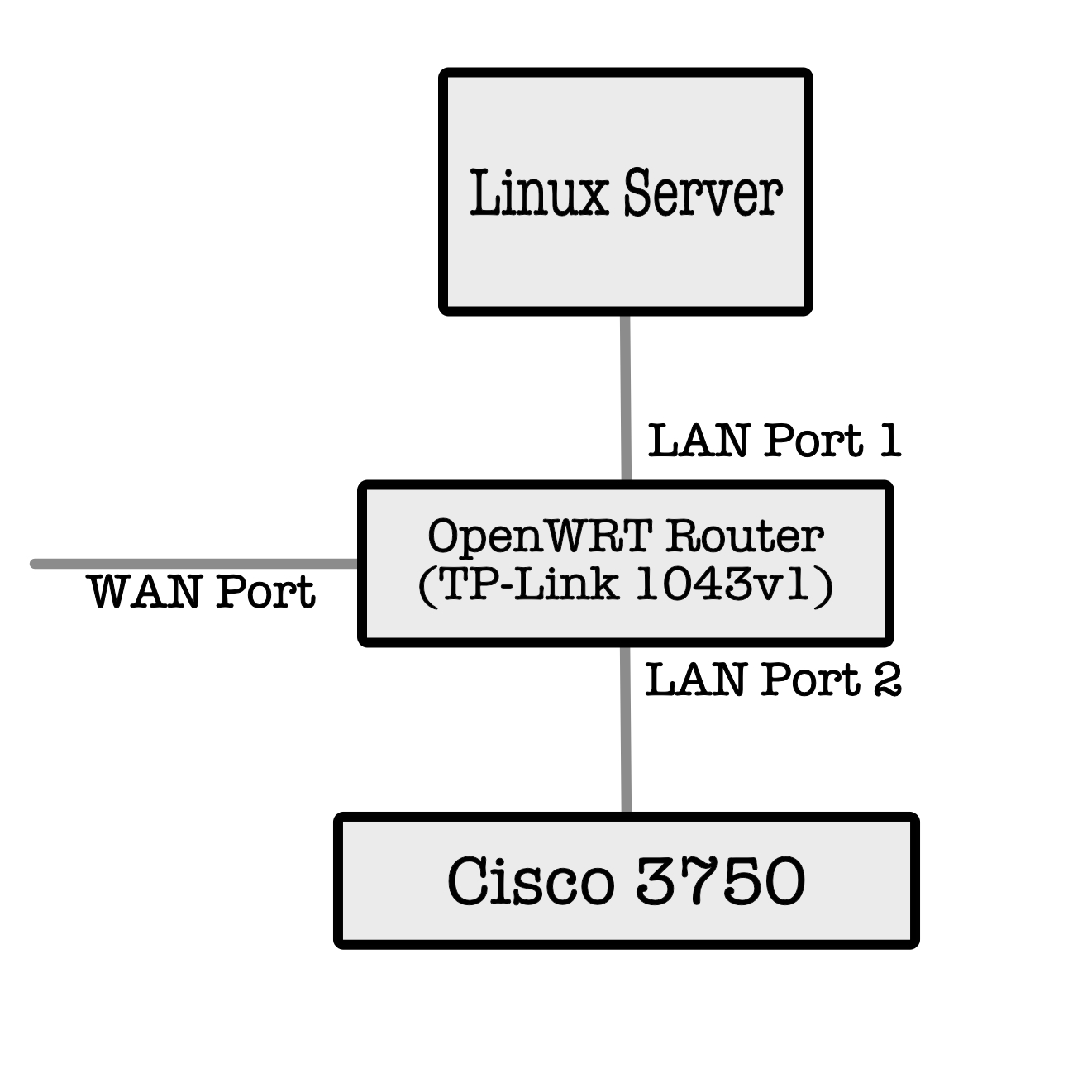
I have tcpdump running on a TP-Link 1043 v1 router with a link between a Linux based server and Cisco switch connected through the switch ports. The issue is the tcpdump only shows routing messages between the various network elements. Running tcpdump on the Linux server I see all the expected packets and the application (server) is working with its connection through the tp-link switch.
Is there any other settings I need to change to show all packets in the capture, I have tried setting the interface (-i option) as br-lan, eth0 and eth0.1 but it has not changed the capture results. The switch section of the tp-link is unmanaged so that I am not reporting any addresses to the connected equipment. The firewall is set to block all traffic from lan to wan. I have remote access to the wan port.
The main function for the tp link router is to capture traffic and write it directly to a connected usb memory stick for analysis.
Thanks for the welcome, if I create a new vlan I presume I need to include both the switch ports and the wan port in the bridge. The equipment wired through the tp link router is connected to a Cisco switch where vlan tagging is configured, would adding the bridge vlan cause issues with the traffic?
I'm not sure why you mentioned WAN. You would create e.g. a second eth0.3 Interface and bridge it to LAN. You would then add that to a LAN port of your choice as untagged. You will turn eth0.1 to off on that port. Then you should be able to capture traffic.
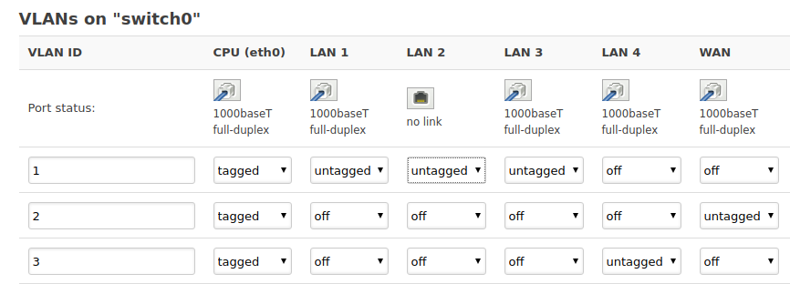
Some switch chips allow mirroring of ports - this may be easier for you. All these switch settings can be seen on the LuCI web GUI at Network > Switch.
I tried adding the extra VLAN and it didn’t go to plan, not long after it was added I lost connection to the Cisco switch. The LAN port status only showed one port in use. I reverted the changes and after a short period both LAN ports showed ok. My router does have the option for port mirroring but this defeats the purpose of the router, I am hoping to use it as and when required as a packet capture box which write the capture to the connected usb memory.
I assume when the VLAN was added and all the ports showed as “off” it should have had no effect on the operation of the LAN ports.
I will probably replicate the monitoring on my home router before attempting anything with the Linux server and Cisco switch, just so I can test it at my leisure with no real consequences if something is wrong.
The reference to the ports being off, was before I reached changing their tag/untag state, it was at that point when the VLAN had just been that shortly after I lost the visibility of one of the LAN ports. After I reverted all changes I wasn’t brave enough to try it again without further guidance.
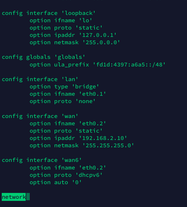
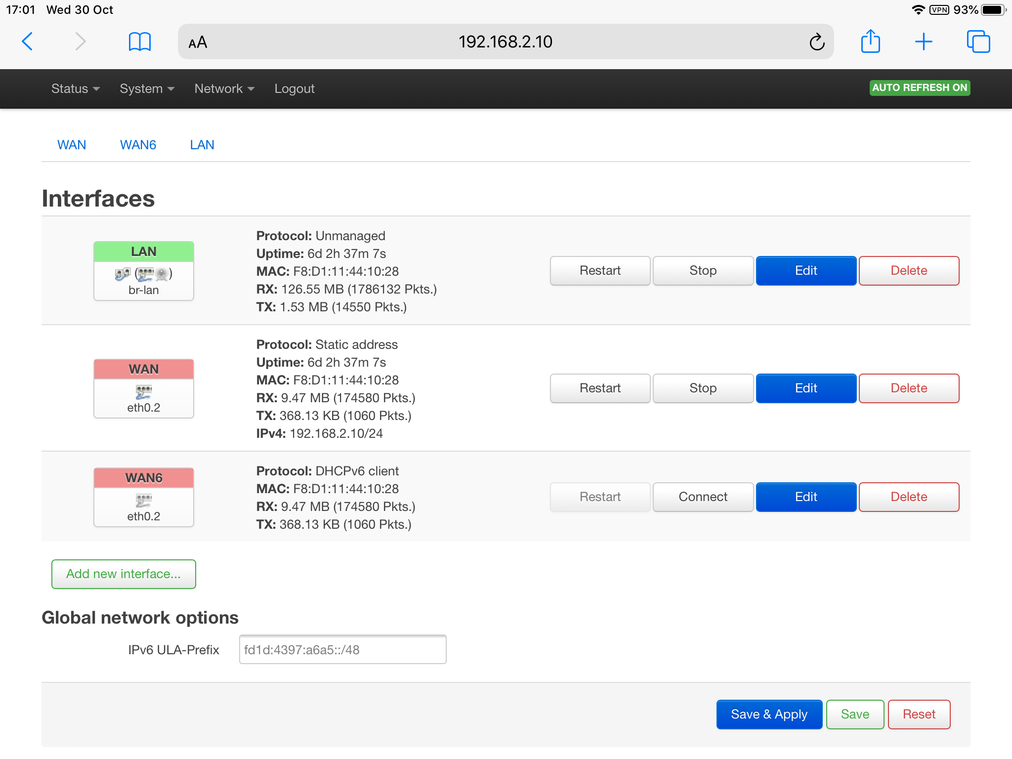
It would really help if you show your configs (i.e. /etc/config/network), perhaps maybe even a screenshot of the Network > Switch page on the LuCI web GUI.
OK, this means you haven't created anything I suggested.
Create another Interface `lan2' as eth0.3 (compare/use LAN setup as your guide)
Add lan2 to the LAN firewall Zone
Browse to Network > Switch and then create another port config for VLAN3. Here's an example to configure the fourth LAN port for another VLAN/Interface:
Thanks, I appreciate your time in trying to provide a solution.
I still get a problem when I create the new vlan port, it results in one of the lan ports showing no connection affecting the connected equipment.
You referred to creating the new interface lan2 but what interfaces is it to cover, at that point the new vlan hasn’t been created.
I thought you mentioned this previously; and I asked that you show your config so we can troubleshoot that. Do not reset to defaults, do not send the default config.
If you followed my steps above, I don't understand how that occurs - so I need to see the completed config.
When you create an OpenWrt Interface (lan2/VLAN3), it initially "covers" nothing
Please create the VLAN by going to Network > Interfaces and adding a lan2 and enumerating eth0.3 as the PHY, this is what "creates" the VLAN - I'm also happy to show more pictures
You then have to un configure a switch port from VLAN 1 and assign it to the new lan2 (VLAN3) - shown above in the screenshot from Network > Switch