Support for RTL838x based managed switches

Thanks! After applying two of the patches, the RTL8214QF is detected, but not properly initialized - I'm quite sure some additional work is needed on the RTL8393M with this combination: MDIO 0x30 and 0x31 are detected as "internal RTL8390 SERDES" while 0x32 and 0x33 are detected as "RTL8214QF PHY". However, the RTL8214QF PHY is only initialized when its base address is a multiple of 4.

I suppose that the internal SERDES needs to be somehow disabled - the U-Boot board config seems to confirm this in rtl8393m_8214b_8214qf_board.c:

    .phy.list = {
        [0] = { .chip = RTK_CHIP_RTL8218B,  .mac_id = 0 , .phy_max = 8 },
        [1] = { .chip = RTK_CHIP_RTL8218B,  .mac_id = 8 , .phy_max = 8 },
        [2] = { .chip = RTK_CHIP_RTL8218B,  .mac_id = 16, .phy_max = 8 },
        [3] = { .chip = RTK_CHIP_RTL8218B,  .mac_id = 24, .phy_max = 8 },
        [4] = { .chip = RTK_CHIP_RTL8218B,  .mac_id = 32, .phy_max = 8 },
        [5] = { .chip = RTK_CHIP_RTL8218B,  .mac_id = 40, .phy_max = 8 },
        [6] = { .chip = RTK_CHIP_RTL8214QF, .mac_id = 48, .phy_max = 4 },
    },   /* .phy.list */

while the same list for rtl8393m_8218b_8218fb_2sfp.c contains

    .phy.list = {
        [0] = { .chip = RTK_CHIP_RTL8218B,  .mac_id = 0 , .phy_max = 8 },
        [1] = { .chip = RTK_CHIP_RTL8218B,  .mac_id = 8 , .phy_max = 8 },
        [2] = { .chip = RTK_CHIP_RTL8218B,  .mac_id = 16, .phy_max = 8 },
        [3] = { .chip = RTK_CHIP_RTL8218B,  .mac_id = 24, .phy_max = 8 },
        [4] = { .chip = RTK_CHIP_RTL8218B,  .mac_id = 32, .phy_max = 8 },
        [5] = { .chip = RTK_CHIP_RTL8218FB, .mac_id = 40, .phy_max = 8 },
        [6] = { .chip = RTK_CHIP_NONE,      .mac_id = 48, .phy_max = 0 },
    },   /* .phy.list */
This comes from the new clock driver that I sent. In your case the LXB speed is not correctly detect. It tells LXB is at 12 MHz which should be 200 MHZ. Maybe we we have some register issues here. I can post a fix if you can send me an memory dump from within UBoot. I think this it is an 838X device so we need 0xb80000fc0 - 0xb80001000 for the PLL registers.

thx.

1 Like

Yes, it's a 838x device. Here you go.

80000fc0: a5a55a5a a5a55a5a 5a5aa5a5 a5a55a5a    ..ZZ..ZZZZ....ZZ
80000fd0: 5a5aa5a5 5555aaaa aaaa5555 5555aaaa    ZZ..UU....UUUU..
80000fe0: aaaa5555 aaaa5555 5555aaaa aaaa5555    ..UU..UUUU....UU
80000ff0: 5555aaaa cc3333cc 33cccc33 cccc3333    UU...33.3..3..33
80001000: 00010000 01234567 00000000 76543210    .....#Eg....vT2.

Looks like that the PHYADDR is shifted by 2. I know they do some hackery by (ab)using the lower 2 bits for other information, so I'm not supprised.

Isn't the .mac_id field the PHYADDR? If that's the case, it's not shifted, right? I'll have a closer look at the U-Boot code later this week.

You are right, looking at my switches equivialent, the mac_id is the port-number it seems.

I need 0xb80000fc0 - 0xb80001000

thx

That's what I get from address 0xb80000fc0
Are you sure the address is correct?

I've tried with one less 0 which gives me this output.

RTL838x# md 0xb8000fc0 
b8000fc0: 00000000 00000000 00000000 00000000    ................
b8000fd0: 00000000 00000000 00000000 00000000    ................
b8000fe0: 00000000 00000000 00000000 00000000    ................
b8000ff0: 00000000 00000000 00000000 00000000    ................
b8001000: 200421e0 20320000 54433830 0404030f     .!. 2..TC80....

Thanks. Your address is right, had one zero too much.

That looks strange. Maybe we have a device, that uses fixed PLL dividers and cannot be instrumented via registers. Can you post a dmesg?

P.S. SORRY I MESSED UP SOC & SW RANGE .

Please send memory dump from bb000fc0-b8001000

You mean 0xbb000fc0 - 0xbb001000?

RTL838x# md 0xbb000fc0
bb000fc0: 00003f07 00004748 0c14530e 2da0cfb8    ..?...GH..S.-...
bb000fd0: 00000000 00000000 2da0cfb8 0000414c    ........-.....AL
bb000fe0: 04018c80 2d20cfb8 00000000 00000000    ....- ..........
bb000ff0: 2da0cfb8 aaaaaaa9 efffffff 00000000    -...............
bb001000: 00000008 00000003 00000000 00000000    ................
1 Like

error found. The LXB mulitplier/divider registers are empty. fd0/fd4. So we get strange timing values. Will provide a fix, that maps to 200MHz in that case.

1 Like

Will be fixed with https://github.com/openwrt/openwrt/pull/10560

3 Likes

I just found this tidbit which I found ironic ...

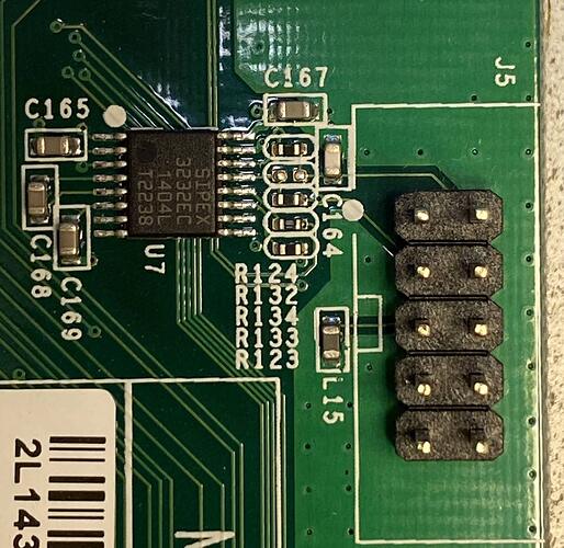
  • Hardware reset button

which we don't have :slight_smile:

Btw, https://nl.farnell.com/alps-alpine/skrtlae010/tactile-switch-0-05a-12vdc-smd/dp/3261831 is I think our switch. I think even the resistors and everything are in place though. They didn't populate the switch because it's at the bottom, and so pick-n-placin this is harder.

Hello friends. Been a while.

I have a Zyxel 1900-24, with serial S142L41000xxx on the underside. (Have a few actually)

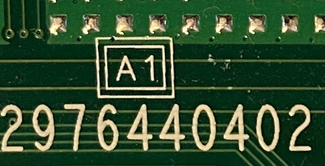
I think it's an A1 - that's what was silk-screened onto the PCB. I can add more photos if those are interesting.

IMG_4411 copy

It's a standard fanless 24 port VLAN switch, with port 25-26 as SFP ports.

Here's a chip breakdown

SIPEX 3232ec 3.3v-5.0v RS-232 serial transceiver
MXIC 25L12835F / M2I10G Flash memory - 3v 128Mbit serial multi IO flash mem, 8 pin pkg)
RTL8231 LED driver for front panel (2x, 1x by SFP ports)
Winbond W9751G8KB-25 512mbit (64mb) working memory
RTL8218B Ethernet transceivers (2x)
RTL8382M EE Ethernet platform

Do I have to test for pinout on the serial?

How does one get openwrt flashed to it? Do I need to tftp boot from uboot or something? Or are there even builds for the -24?

The wiki doesn't give much info https://openwrt.org/toh/hwdata/zyxel/zyxel_gs1900-24_v1

===
Board CFG:

# show board
****************************
 GS1900-24
****************************
============================
 Board GPIO
============================
Device  Pin  Direction  Default  Current
------- ---- ---------- -------- --------
INT     0    OUT        0        0
INT     1    OUT        1        1
INT     2    OUT        0        0
INT     3    OUT        0        0
INT     8    OUT        1        1
INT     9    OUT        1        1
INT     12   IN         0        0
INT     13   OUT        1        1
INT     14   OUT        1        1
INT     15   OUT        1        1
INT     16   IN         0        0
INT     17   OUT        1        1
INT     18   OUT        0        0
INT     19   IN         0        0
INT     20   OUT        1        1
INT     21   IN         0        0
INT     22   IN         0        0
INT     23   OUT        1        1
EXT     0    IN  (IN  ) 0        0
EXT     1    IN  (IN  ) 0        0
EXT     2    IN  (IN  ) 0        1
EXT     3    IN  (IN  ) 0        1
EXT     4    IN  (IN  ) 0        0
EXT     5    OUT (OUT ) 1        1
EXT     6    OUT (OUT ) 1        1
EXT     7    IN  (IN  ) 0        1
EXT     8    OUT (OUT ) 1        1
EXT     13   OUT (OUT ) 0        0
EXT     14   OUT (OUT ) 0        0
EXT     15   OUT (OUT ) 0        0
EXT     16   OUT (OUT ) 0        0
EXT     17   OUT (IN  ) 0        0
EXT     18   OUT (IN  ) 0        0
EXT     22   IN  (IN  ) 0        1
EXT     23   OUT (OUT ) 0        0
EXT     24   OUT (OUT ) 0        1
EXT     25   OUT (OUT ) 0        1
EXT     26   IN  (IN  ) 0        1
EXT     27   IN  (IN  ) 0        1
EXT     28   IN  (IN  ) 0        1
EXT     29   OUT (OUT ) 0        0
EXT     30   OUT (OUT ) 0        1
EXT     31   OUT (OUT ) 0        1
EXT     32   IN  (IN  ) 0        1
EXT     33   IN  (IN  ) 0        1
EXT     34   OUT (OUT ) 1        1

============================
 Board Configuration
============================
====== Port ==================
Type       Usr  Phy     Media       Speed          Duplex   Attr
---------- ---- ------- ----------- -------------- -------- -------
1000M      1    (0) 0   Copper      (A) ALL        Auto     0
1000M      2    (0) 1   Copper      (A) ALL        Auto     0
1000M      3    (0) 2   Copper      (A) ALL        Auto     0
1000M      4    (0) 3   Copper      (A) ALL        Auto     0
1000M      5    (0) 4   Copper      (A) ALL        Auto     0
1000M      6    (0) 5   Copper      (A) ALL        Auto     0
1000M      7    (0) 6   Copper      (A) ALL        Auto     0
1000M      8    (0) 7   Copper      (A) ALL        Auto     0
1000M      9    (0) 8   Copper      (A) ALL        Auto     0
1000M      10   (0) 9   Copper      (A) ALL        Auto     0
1000M      11   (0) 10  Copper      (A) ALL        Auto     0
1000M      12   (0) 11  Copper      (A) ALL        Auto     0
1000M      13   (0) 12  Copper      (A) ALL        Auto     0
1000M      14   (0) 13  Copper      (A) ALL        Auto     0
1000M      15   (0) 14  Copper      (A) ALL        Auto     0
1000M      16   (0) 15  Copper      (A) ALL        Auto     0
1000M      17   (0) 16  Copper      (A) ALL        Auto     0
1000M      18   (0) 17  Copper      (A) ALL        Auto     0
1000M      19   (0) 18  Copper      (A) ALL        Auto     0
1000M      20   (0) 19  Copper      (A) ALL        Auto     0
1000M      21   (0) 20  Copper      (A) ALL        Auto     0
1000M      22   (0) 21  Copper      (A) ALL        Auto     0
1000M      23   (0) 22  Copper      (A) ALL        Auto     0
1000M      24   (0) 23  Copper      (A) ALL        Auto     0
1000M      25   (0) 24  Fiber       (A) ALL        Auto     0
1000M      26   (0) 26  Fiber       (A) ALL        Auto     0


====== Fiber =================
Fiber Port Number: 2

------------ Fiber Detect
LPort  Present  MediaChg  OE Status              LOS Status
------ -------- --------- ---------------------- ----------------------
24     OE       OE        Enabled  (GPIO:EXT_26) Enabled  (GPIO:EXT_27)
25     OE       OE        Enabled  (GPIO:EXT_32) Enabled  (GPIO:EXT_33)

------------ Fiber Optical
LPort  SMI DEV  SMI TYPE  ID    Delay   SCK    SDA
------ -------- --------- ----- ------- ------ ------
24     SFP1     8 BITS    0x50  4000    EXT_25 EXT_24
25     SFP2     8 BITS    0x50  4000    EXT_31 EXT_30

------------ Fiber TX Disable
LPort  GPIO
------ ------
24     EXT_23
25     EXT_29


====== Button ================

------------ Reset Button
GPIO: EXT_3
Timer: 3(sec)  Action: Reboot
Timer: 6(sec)  Action: Restore Factory


====== Led ===================
SYS (REG)
ALARM (REG)


====== Reset =================
Type: GPIO
GPIO: EXT_5


====== WatchDog ==============
Type: REG
1 Like

from the page you linked above, the linked git commit https://git.openwrt.org/?p=openwrt/openwrt.git;a=commit;h=d1a8690742fc448b764cf5fb448b6459c13e3ccc also has install instructions departing from the OEM WebGUI.

Try those? (Hooking up serial as well is not a bad idea in any case)

1 Like

Do you have any understanding as to what "v1" corresponds to? i.e. my A1? Or does it cover multiple hardware models?

Newer models carry a v2 in the product name like GS1900v2.

2 Likes

Does anyone here know how to flash back? Just upload Zyxels firmware file via openwrt and flash?

You can switch to the partition that contains the 2nd firmware image (which would still be OEM) and reinstall the OEM firmware onto the other partition from there. You should be able to indicate the partition to be flashed in the OEM web UI.

If it helps, I described the openwrt boot and install procedure for another RTL9301 device on svanheule.net wiki which is quite similar if not even same for the zyxel.

1 Like