Could you please modify the submission to be specific as to the supported versions? The earlier versions use different SOCs that also could eventually gain support. The A and B versions use a Marvell Kirkwood SOC and there was a previous effort to support OpenWrt on those.
You can find everything that we know about which models and version are supported by the development branch for the rtl83xx chips here
Devices which we have tested already can be found here:
Unlike WiFi routers where there is a new generation of hardware every 2nd year, the designs of these switches have usually been stable since 10 years. However in particular DLink seems to be changing the platform for similarly named products on a regular basis, while the specs do not really change.
If you want to find out whether your device and version is supported, the easiest is to download the firmware from the vendor page for that version. Unpack it, use "binwalk -e" to extract the firmware into its components and then use "strings * | grep RTL" to look for signatures of the SDK.
If you find references to RTL8380 and RTL8390 plus maybe older versions like the RTL8328, then it is very likely supported with only some modifications in the .dts. If there are references also to RTL9300 and RTL9310, then it is probably supported, this is the latest version 3 of the SDK from Realtek also for multi-gig switches (which are presently not supported!) but might need some development still for modern features like newer PHYs or USB, even if these devices still use the RTL838X/9X chips.
If you learn something about a particular device, it would be great to post it, or edit the above wiki pages yourself (ask biot for write permission).
3 Likes
I recently bought a TP-Link T1600G-52PS V4 switch (48Port PoE+) that seems to be based on a Realtek chip (judging from the GPL dump). The firmware upgrade images look encrypted, at least binwalk outputs nothing.
I just did an initial disassembly and could identify a few components (the SoC is covered by a big heatsink that I don't want to remove):
- 256MByte DDR3
- 32MByte SPI Flash
- RTL8214 (probably for the SFP slots)
There is a four-pin serial header, 38400 8n1. GND is easy to spot, it's either TX, RX, GND, VCC or RX, TX, GND, VCC I didn't check it further.
Unfortunately, the boot log is not very verbose:
Hit any key to stop autoboot:  1 <0x08><0x08><0x08> 0

Begin to startup system, please wait a moment...

Starting kernel ...


***************** User Access Login ********************

User:
Interrupting the boot loader leads to this:
Hit any key to stop autoboot:  1 <0x08><0x08><0x08> 0
		*********************************************
		*         TP-LINK  BOOTUTIL(v1.0.0)         *
		*********************************************
		Copyright (c) 2019 TP-LINK Tech. Co., Ltd
		Create Date: Aug 14 2019 - 09:58:42

   Boot Menu
0  - Print this boot menu
1  - Reboot
2  - Reset
3  - Start
4  - Activate Backup Image
5  - Display image(s) info
6  - Password recovery
This seems very similar to the T1500G posted above - I suppose, I have to flash a new (full) U-Boot. I've only got a cheap CH340-based SOIC-8 clip/flasher, but the flash IC is SOIC-16. What do you use/can I use to flash it?
I've got about a month to toy with the switch, then it needs to run our house network. I do have some experience in porting ath79 and lantiq targets, is there anything vastly different or important for this target?
1 Like
I got the T1600G-52PS v4 firmware decrypted (the firmware image is DES encrypted, the IV and KEY can be found in the U-Boot source code) and ran the binwalk -e -M command followed by string * | grep RTL on the files:
RTL8380
RTL8328
RTL8390
RTL8390/80/28 ICTL
RTL8390/80/28 IRQ cascade1
RTL8390/80/28 IRQ cascade2
RTL8390/80/28 IRQ cascade3
RTL8390/80/28 IRQ cascade4
RTL8390/80/28 IRQ cascade5
Grepping for boardmodel in the decrypted firmware upgrade outputs:
boardmodel=RTL8393M_8218B_8214QF_DEMO
Looks promising, right? Now how to best flash a new U-Boot?
2 Likes
I would start with building a new u-boot based on the GPL-code
https://static.tp-link.com/resources/gpl/t1600g-52ps-v4_gpl.tar.gz
and make sure you get the full menu as posted above. Could you explain how you managed to extract the DES key? With regards to porting, the best starting point is to use the .dts of the Zyxel GS-1900-48 as the port-layout is probably identical and the board will be based on the RTL8393 SoC, too. Please keep us posted!
That was actually easy: I was poking through the GPL code and found the file ldk_realtek/realtek-V2.1.6.pre2/u-boot-2011.12/common/DesDecode.c. It contains the variables des_key and des_iv - to my big surprise, they were correct.
Then I used openssl to decode the image:
openssl enc -d -des-cbc -in encrypted.bin -out decrypted.bin -nosalt -nopad -p -iv $IV -K $KEY
Building it shouldn't be a problem, it seems that defining UBOOT_DEBUG might be sufficient (there is a #ifdef UBOOT_DEBUG in bootapp.c that guards most of the commands), but I have yet to find a way to transfer it to the chip. I'll order an SOIC16 testing clip and see if I can use the CH341 or a Raspberry Pi as flasher.
I've been thinking a bit about the other components: How did you figure out the protocol for configuring the PoE injector?
1 Like
Went to the biot.com wiki, but could not find a link to request an account. How do I get an account to add additional devices with detailed chipset information?
Usually there is an ARM microcontroller on the board which controls the actual PoE controller chip which should be from Broadcom (the alternative is that there is only a PowerDsine chip). The ARM microcontroller (we have seen Nuvoton and STM) talks uart to the RTL83xx SoC and SPI to the BCM chip. You can sniff the uart either on the pins of the ARM microcontroller or sometimes on a pin-header close to the microcontroller. In addition there is usually an ARM SWD header to program the microcontroller. On biot's wiki there is a description of the PoE protocol as far as it is understood. blogic as written a daemon talking ubus to control it, there might be the need to put the right values for your switch in, though.
While waiting for the SOIC16 clip to arrive, I had a look at the TP-Link firmware upgrade file structure - in order to allow future upgrades from stock. I've created a Wiki page with what I know so far (IMHO it's very different to the known TP-Link router firmware formats):
Btw, has anybody done a flash dump of one of the TP-Link switches with the same firmware scheme? I'd be interested in what actually ends up on the flash (T1500G or T2500G).
1 Like
I am so happy to finally see OpenWrt support for a major switch SoC platform. Just got myself a ZyXEL GS1900-10HP, which I assumed should be a piece-of-cake to get up and running. But I guess I am a little too stupid for this....
I checked out the current rtl83xx_dev branch from https://github.com/bkobl/openwrt.git and built a GS1900-10HP image using mostly default settings. But trying to load the sysupgrade.bin in the OEM web GUI results in:
Firmware Validation Error
Invalid image signature
So I thought I'd simply tftpboot the initramfs image and see where I could get from there. Ran
rtk network on
tftpboot 10hp.bin
where 10hp.bin is the name of the initramfs file on my tftp server. And I can see that uboot starts a tftp transfer. But it's just incredibly slow with a number of timouts, eventually failing to complete. I guess there either is some magic tftp setting I can't figure out, or some magic switch setting. I do notice that the network seems to be completely dead after such an attempt. I have link on both sides (or a green LED on the GS1900 at least), but I can't ping either way anymore. Doing
rtk network off
rtk network on
does not help either. I tried a few different ports, even including the SFP ports, with exactly the same result. Only way I found to get uboot networking up again is by power cycling the switch.
So I seem to be stuck there. Can't tftp boot and can't sysupgrade using the OEM web gui. Any hints on how to proceed?
I guess you have the wrong load address and you are overwriting the u-boot code. Try
tftpboot 0x84f00000 192.168.1.150:openwrt-rtl838x-zyxel_gs1900-10hp-initramfs-kernel.bin
And then
bootm
Make sure you don't try to run the sysupgrade code here.
Indeed, official Zyxel GS1900-10HP support is still missing, with the possibility to flash it from the OEM web-interface. In general, however, the device is very well supported, you should be able to flash out of the initram image (not tested!). Try also the poe package with blogic's PoE daemon from that repository. Any feedback is very wellcome.
Thanks! Yes, that made all the difference.
Tried looking at the OEM firmware, but can't say I recognize the header format immediately. Nor does "file". Do you happen to know if it is something used by other supported devices , or if this is a specific wrapper for these ZyXEL switches?
EDIT: ok, so that's just a standard uImage header with 0x83800000 as magic and a typical ZyXEL version string?
Yes, the level of support was one of the reasons I went for this model. And the fact that it has a console header which is accessible without even opening the case. ZyXEL are often nice enough to solder a header on their console ports and leave the console fully functional. But it's the first time I've seen them make an access hole like this. Did see something similar on a D-Link camera, but that's another story.
I do plan to use the PoE daemon, and maybe extend it with a snmp plugin if I can make that fly. I love the Power Ethernet MIB (RFC3621) support on more expensive switches. it would be nice to have something similar for these devices too, for both monitoring and control.
For now I seem to have some issues building lua-rs232. And the rtl83xx-poe package is messed up by a DOS editor. Will provide better feedback and patches when I get around to looking at it. First I'll play with the basic features and see if I can manage to flash OpenWrt with bricking the switch ![]()
EDIT: no problem there. just write the sysupgrade image to the firmware partition and make sure it is configured as active by running
setsys bootpartition=0
savesys
in the bootloader. I assume OpenWrt can't (yet) boot from the second partition since mtd5 is hard coded as "firmware". But this can be nice for keeping an OEM backup installation, anyway.
I don't seem to have much success with th PoE daemon unfortunately. I enabled some of the debug prints and added one on send, just to see that it's actually sending what I expect. The daemon starts up fine and seems to communicate with the controller. But I am unable to turn on power on any port, whether on startup or by ubus calls.
Starting with ports 1 to 3 enabled:
root@OpenWrt:~# /tmp/poe.lua  65 1 1 1 0 0 0 0 0
OK, port open with values 'device: /dev/ttyS1, baud: 19200, data bits: 8, parity: none, stop bits: 1, flow control: off'
send 12 bytes: 20 01 ff ff ff ff ff ff ff ff ff 18
valid: Reply:  20 01 02 08 01 e1 21 16 00 05 04 4d
send 12 bytes: 18 01 00 00 00 00 00 ff ff ff ff 15
valid: Reply:  18 01 00 00 ff ff ff ff ff ff ff 12
send 12 bytes: 17 00 02 ff ff ff ff ff ff ff ff 11
valid: Reply:  17 00 00 ff ff ff ff ff ff ff ff 0f
send 12 bytes: 06 00 01 ff ff ff ff ff ff ff ff ff
valid: Reply:  06 00 00 ff ff ff ff ff ff ff ff fe
send 12 bytes: 00 00 00 00 ff ff ff ff ff ff ff f9
valid: Reply:  00 00 00 00 ff ff ff ff ff ff ff f9
send 13 bytes: 00 00 00 00 ff ff ff ff ff ff ff f9
valid: Reply:  00 00 00 00 ff ff ff ff ff ff ff f9
send 12 bytes: 00 01 01 00 ff ff ff ff ff ff ff fb
valid: Reply:  00 01 01 00 ff ff ff ff ff ff ff fb
send 13 bytes: 00 01 01 00 ff ff ff ff ff ff ff fb
valid: Reply:  00 01 01 00 ff ff ff ff ff ff ff fb
send 12 bytes: 00 02 02 00 ff ff ff ff ff ff ff fd
valid: Reply:  00 02 02 00 ff ff ff ff ff ff ff fd
send 13 bytes: 00 02 02 00 ff ff ff ff ff ff ff fd
valid: Reply:  00 02 02 00 ff ff ff ff ff ff ff fd
send 12 bytes: 00 03 03 00 ff ff ff ff ff ff ff ff
valid: Reply:  00 03 03 00 ff ff ff ff ff ff ff ff
send 13 bytes: 00 03 03 00 ff ff ff ff ff ff ff ff
valid: Reply:  00 03 03 00 ff ff ff ff ff ff ff ff
send 12 bytes: 00 04 04 00 ff ff ff ff ff ff ff 01
valid: Reply:  00 04 04 00 ff ff ff ff ff ff ff 01
send 13 bytes: 00 04 04 00 ff ff ff ff ff ff ff 01
valid: Reply:  00 04 04 00 ff ff ff ff ff ff ff 01
send 12 bytes: 00 05 05 00 ff ff ff ff ff ff ff 03
valid: Reply:  00 05 05 00 ff ff ff ff ff ff ff 03
send 13 bytes: 00 05 05 00 ff ff ff ff ff ff ff 03
valid: Reply:  00 05 05 00 ff ff ff ff ff ff ff 03
send 12 bytes: 00 06 06 00 ff ff ff ff ff ff ff 05
valid: Reply:  00 06 06 00 ff ff ff ff ff ff ff 05
send 13 bytes: 00 06 06 00 ff ff ff ff ff ff ff 05
valid: Reply:  00 06 06 00 ff ff ff ff ff ff ff 05
send 12 bytes: 00 07 07 00 ff ff ff ff ff ff ff 07
valid: Reply:  00 07 07 00 ff ff ff ff ff ff ff 07
send 13 bytes: 00 07 07 00 ff ff ff ff ff ff ff 07
valid: Reply:  00 07 07 00 ff ff ff ff ff ff ff 07
send 12 bytes: 02 00 01 ff ff ff ff ff ff ff ff fb
valid: Reply:  02 00 00 ff ff ff ff ff ff ff ff fa
send 12 bytes: 1d 00 00 07 ff ff ff ff ff ff ff 1d
valid: Reply:  1d 00 00 00 ff ff ff ff ff ff ff 16
send 12 bytes: 1d 00 01 06 ff ff ff ff ff ff ff 1d
valid: Reply:  1d 00 01 00 ff ff ff ff ff ff ff 17
send 12 bytes: 1d 00 02 05 ff ff ff ff ff ff ff 1d
valid: Reply:  1d 00 02 00 ff ff ff ff ff ff ff 18
send 12 bytes: 1d 00 03 04 ff ff ff ff ff ff ff 1d
valid: Reply:  1d 00 03 00 ff ff ff ff ff ff ff 19
send 12 bytes: 1d 00 04 03 ff ff ff ff ff ff ff 1d
valid: Reply:  1d 00 04 00 ff ff ff ff ff ff ff 1a
send 12 bytes: 1d 00 05 02 ff ff ff ff ff ff ff 1d
valid: Reply:  1d 00 05 00 ff ff ff ff ff ff ff 1b
send 12 bytes: 1d 00 06 01 ff ff ff ff ff ff ff 1d
valid: Reply:  1d 00 06 00 ff ff ff ff ff ff ff 1c
send 12 bytes: 1d 00 07 00 ff ff ff ff ff ff ff 1d
valid: Reply:  1d 00 07 00 ff ff ff ff ff ff ff 1d
send 12 bytes: 25 01 ff ff ff ff ff ff ff ff ff 1d
valid: Reply:  25 01 ff 00 00 00 00 00 00 ff ff 23
send 12 bytes: 18 01 00 02 8a 00 46 ff ff ff ff e7
valid: Reply:  18 01 00 00 ff ff ff ff ff ff ff 12
send 12 bytes: 23 01 ff ff ff ff ff ff ff ff ff 1b
valid: Reply:  23 01 00 00 02 dc 07 02 ff ff 00 09
send 12 bytes: 11 00 00 01 ff ff ff ff ff ff ff 0b
valid: Reply:  11 00 00 00 ff ff ff ff ff ff ff 0a
send 12 bytes: 13 00 00 02 ff ff ff ff ff ff ff 0e
valid: Reply:  13 00 00 00 ff ff ff ff ff ff ff 0c
send 12 bytes: 15 00 00 01 ff ff ff ff ff ff ff 0f
valid: Reply:  15 00 00 00 ff ff ff ff ff ff ff 0e
send 12 bytes: 10 00 00 03 ff ff ff ff ff ff ff 0c
valid: Reply:  10 00 00 00 ff ff ff ff ff ff ff 09
send 12 bytes: 11 01 01 01 ff ff ff ff ff ff ff 0d
valid: Reply:  11 01 01 00 ff ff ff ff ff ff ff 0c
send 12 bytes: 13 01 01 02 ff ff ff ff ff ff ff 10
valid: Reply:  13 01 01 00 ff ff ff ff ff ff ff 0e
send 12 bytes: 15 01 01 01 ff ff ff ff ff ff ff 11
valid: Reply:  15 01 01 00 ff ff ff ff ff ff ff 10
send 12 bytes: 10 01 01 03 ff ff ff ff ff ff ff 0e
valid: Reply:  10 01 01 00 ff ff ff ff ff ff ff 0b
send 12 bytes: 11 02 02 01 ff ff ff ff ff ff ff 0f
valid: Reply:  11 02 02 00 ff ff ff ff ff ff ff 0e
send 12 bytes: 13 02 02 02 ff ff ff ff ff ff ff 12
valid: Reply:  13 02 02 00 ff ff ff ff ff ff ff 10
send 12 bytes: 15 02 02 01 ff ff ff ff ff ff ff 13
valid: Reply:  15 02 02 00 ff ff ff ff ff ff ff 12
send 12 bytes: 10 02 02 03 ff ff ff ff ff ff ff 10
valid: Reply:  10 02 02 00 ff ff ff ff ff ff ff 0d
send 12 bytes: 11 03 03 01 ff ff ff ff ff ff ff 11
valid: Reply:  11 03 03 00 ff ff ff ff ff ff ff 10
send 12 bytes: 13 03 03 02 ff ff ff ff ff ff ff 14
valid: Reply:  13 03 03 00 ff ff ff ff ff ff ff 12
send 12 bytes: 15 03 03 01 ff ff ff ff ff ff ff 15
valid: Reply:  15 03 03 00 ff ff ff ff ff ff ff 14
send 12 bytes: 10 03 03 03 ff ff ff ff ff ff ff 12
valid: Reply:  10 03 03 00 ff ff ff ff ff ff ff 0f
send 12 bytes: 11 04 04 01 ff ff ff ff ff ff ff 13
valid: Reply:  11 04 04 00 ff ff ff ff ff ff ff 12
send 12 bytes: 13 04 04 02 ff ff ff ff ff ff ff 16
valid: Reply:  13 04 04 00 ff ff ff ff ff ff ff 14
send 12 bytes: 15 04 04 01 ff ff ff ff ff ff ff 17
valid: Reply:  15 04 04 00 ff ff ff ff ff ff ff 16
send 12 bytes: 10 04 04 03 ff ff ff ff ff ff ff 14
valid: Reply:  10 04 04 00 ff ff ff ff ff ff ff 11
send 12 bytes: 11 05 05 01 ff ff ff ff ff ff ff 15
valid: Reply:  11 05 05 00 ff ff ff ff ff ff ff 14
send 12 bytes: 13 05 05 02 ff ff ff ff ff ff ff 18
valid: Reply:  13 05 05 00 ff ff ff ff ff ff ff 16
send 12 bytes: 15 05 05 01 ff ff ff ff ff ff ff 19
valid: Reply:  15 05 05 00 ff ff ff ff ff ff ff 18
send 12 bytes: 10 05 05 03 ff ff ff ff ff ff ff 16
valid: Reply:  10 05 05 00 ff ff ff ff ff ff ff 13
send 12 bytes: 11 06 06 01 ff ff ff ff ff ff ff 17
valid: Reply:  11 06 06 00 ff ff ff ff ff ff ff 16
send 12 bytes: 13 06 06 02 ff ff ff ff ff ff ff 1a
valid: Reply:  13 06 06 00 ff ff ff ff ff ff ff 18
send 12 bytes: 15 06 06 01 ff ff ff ff ff ff ff 1b
valid: Reply:  15 06 06 00 ff ff ff ff ff ff ff 1a
send 12 bytes: 10 06 06 03 ff ff ff ff ff ff ff 18
valid: Reply:  10 06 06 00 ff ff ff ff ff ff ff 15
send 12 bytes: 11 07 07 01 ff ff ff ff ff ff ff 19
valid: Reply:  11 07 07 00 ff ff ff ff ff ff ff 18
send 12 bytes: 13 07 07 02 ff ff ff ff ff ff ff 1c
valid: Reply:  13 07 07 00 ff ff ff ff ff ff ff 1a
send 12 bytes: 15 07 07 01 ff ff ff ff ff ff ff 1d
valid: Reply:  15 07 07 00 ff ff ff ff ff ff ff 1c
send 12 bytes: 10 07 07 03 ff ff ff ff ff ff ff 1a
valid: Reply:  10 07 07 00 ff ff ff ff ff ff ff 17
send 12 bytes: 00 00 00 01 ff ff ff ff ff ff ff fa
valid: Reply:  00 00 00 00 ff ff ff ff ff ff ff f9
send 12 bytes: 00 01 01 01 ff ff ff ff ff ff ff fc
valid: Reply:  00 01 01 00 ff ff ff ff ff ff ff fb
send 12 bytes: 00 02 02 01 ff ff ff ff ff ff ff fe
valid: Reply:  00 02 02 00 ff ff ff ff ff ff ff fd
Enabling port 4:
root@OpenWrt:/# ubus -v call poe port '{"enable":true,"port":4}'
{

}
send 12 bytes: 00 03 03 01 ff ff ff ff ff ff ff 00
valid: Reply:  00 03 03 00 ff ff ff ff ff ff ff ff
As you can see, all the enable attempts return a valid reply with power disabled. I tried adding a port status request on enable, and it confirmst that the port is disabled:
send 12 bytes: 00 02 02 01 ff ff ff ff ff ff ff fe
valid: Reply:  00 02 02 00 ff ff ff ff ff ff ff fd
send 12 bytes: 21 02 02 ff ff ff ff ff ff ff ff 1d
valid: Reply:  21 02 02 00 00 00 00 00 00 00 00 25
On Zyxel switches, there appear to be two extra initialisation commands that I don't see in your trace. Can you try adding them to the init procedure?
Regarding the TP-Link T1600G-52PS: Finally, my SOIC16 clip arrived! I was able to flash a self-compiled U-Boot and my switch still works and offers me a full U-Boot menu.
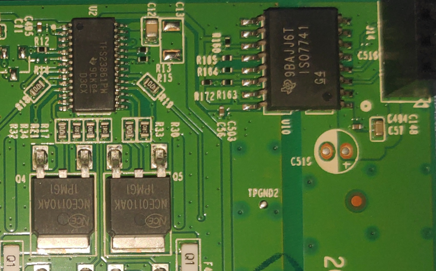
I also took the PoE board off: It contains, once again, different ICs:
- 12x TI TPS23861PW
- 1x TI 9BAJJ6T ISO7741
This ISO7741 is a quad-channel digital isolator - seems as if the PSE controllers were directly controlled via i2c by the SoC?
2 Likes
Interesting! I like this kind of PoE implementation more than the MCU-managed Broadcoms, since these have a fixed (and publicly documented) control interface.
You can also run the TPS23861 in fully auto mode, it's a smart thing so it will detect whether the PD device is preset at all.
Otherwise, there are semi-auto and full manual mode over I2C too, it's easy to debug since you simply read the values directly.
And there are full docs in the TI datasheet.
Sorry for interfering with your thread as I have no RTL boards, was just following it and have seen a reference to POE PSE IC we use on our boards.
2 Likes
That's what I thought! It should be a matter of identifying the i2c addresses and implementing a daemon.
Ah perfect, do you have some management code that you can share or can you point me towards a reference implementation?
But first I should get OpenWrt up and running...
Unfortunately, not yet, we don't do much messing with its controls as there is no need.
We are planning to push the Linux driver for at least monitoring the values in a human way upstream as we get everything sorted, there are some higher priorities now.
As I said, by default it is in automatic mode and it should work fine in that.
If you need to force it to do something, well then the design is messed up.
All of the registers and everything is in the TI datasheet that is public, there is also MSP430 based reference code:
https://www.ti.com/product/TPS23861#design-development##software-development
1 Like
We were discussing earlier whether the PoE stuff belongs in userspace or the kernel. With set-in-stone protocols such as TI's, or Microsemi's from the PD69xxx series, I think you have a far better chance of ever getting this into the kernel. Then you can integrate it with the sensors framework etc.
The MCU used with the Broadcom PSE doesn't have a fixed firmware, it can easily be upgraded to a new version. I've seen a number of different versions by now, running on different MCUs. I strongly doubt anything as volatile as this interface would ever be considered for inclusion in the kernel.
1 Like