I don't think that's correct. A0 can be muxed as the sys-led, A2/A3 as the MDIO bus for an RTL8231. The five JTAG pins are muxed on B2-B6, but JTAG normally isn't used. Seeing the RTL8231 implementation, I wouldn't put it past TP-Link to use more GPIOs for bit-banged I2C busses. There should be 24 GPIO lines in total on an RTL838x. I haven't found all control bits for them yet, but of course it's also possible not all of them can be muxed to a pin.
Going by the thickness of the traces, I think this picture shows 6 pull-ups per SFP-module:
SCK (possibly shared)
SDA
Loss Of Signal
Module absent
Tx disable (possibly shared)
Tx fault
If these are all linked to the SoC, that would require between 18 (shared SCK and Tx disable) and 24 GPIO lines. This would be, by far, the largest number of SoC GPIO lines I've ever seen used on an RTL838x device!
I was just playing around with the firmware upload feature in the stock firmware, when I noticed that since I flashed the full u-boot, communication is now only working on the SoC internal PHY ports on stock firmware.
port 0 patch ready fail 0
port 1 patch ready fail 0
port 2 patch ready fail 0
port 3 patch ready fail 0
port 4 patch ready fail 0
port 5 patch ready fail 0
port 6 patch ready fail 0
port 7 patch ready fail 0
port 8 patch ready fail 0
port 9 patch ready fail 0
port 10 patch ready fail 0
port 11 patch ready fail 0
port 12 patch ready fail 0
port 13 patch ready fail 0
port 14 patch ready fail 0
port 15 patch ready fail 0
port 16 patch ready fail 0
port 17 patch ready fail 0
port 18 patch ready fail 0
port 19 patch ready fail 0
port 20 patch ready fail 0
port 21 patch ready fail 0
port 22 patch ready fail 0
port 23 patch ready fail 0
Getting those on stock firmware boot. Indeed there seems to be some trickery going on.
Maybe the external PHY's would be correctly detected in my openwrt image with stock u-boot in the flash?
TP-Link's firmware format seems to be a bit mixed up compared to openwrt default:
$ binwalk T1600G-28TSv3_en_3.0.6_\[20200805-rel55968\]_up.bin

DECIMAL       HEXADECIMAL     DESCRIPTION
--------------------------------------------------------------------------------
512           0x200           Squashfs filesystem, little endian, version 4.0, compression:lzma, size: 4173556 bytes, 47 inodes, blocksize: 131072 bytes, created: 2020-08-05 07:42:00
4174336       0x3FB200        uImage header, header size: 64 bytes, header CRC: 0xF85DCDDC, created: 2020-08-05 07:41:41, image size: 3869836 bytes, Data Address: 0x80000000, Entry Point: 0x80003710, data CRC: 0xDB7329CD, OS: Linux, CPU: MIPS, image type: OS Kernel Image, compression type: gzip, image name: "3.0.0"
4174400       0x3FB240        gzip compressed data, maximum compression, has original file name: "vmlinux_org.bin", from Unix, last modified: 2020-08-05 07:41:41
8306376       0x7EBEC8        Copyright string: "Copyright (c) "
8328464       0x7F1510        CRC32 polynomial table, little endian
8354164       0x7F7974        JFFS2 filesystem, big endian
Yes, I started implementing this into the image generation routine. If thats not already done by someone?
Edit: Bodged together a firmware image and uploaded it via the stock webinterface.
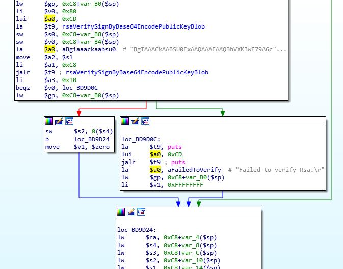
Failed to verify Rsa.
is dumped on serial console. Their core binary in the stock firmware seems to be really verifying it. With a hardcoded version of the key inside the binary, identical to the one in the firmware file, though.
I think you just have to append the rsa key at the end of the image. It is a fixed key that seems to be the same for all tp-link switches since forever.
The pubkey is in the jffs part but it seems to be not used by the binary handling the firmware upgrade. The last 128 bytes seems to be the signature created with tplinks private key? Or did I misunderstand something?
Yeah, i meant the signature in the last 128 bytes. you could check with various firmware files, but to me it looked as if the signature was generic and not actually dependend on the firmware. but maybe i mixed something up there during testing. can't currently check myself, i'm off to work.
Comparing the T1600G-18TSv2 with T1600G-28TSv3, the signature in the final 128 bytes is different. On the EAP2x5 devices it's possible to disable the signature check though. Anything similar in the code here?
On the EAP225v1 and EAP245v1 you needed to patch the binary that performs the upgrade. On later devices in that series you can just run cliclientd stopcs as an unprivileged user to disable the signature checks.
Thanks for that information. On first glance it seems TP-Link does not include this feature on their switches. Was not able to find cliclientd nor stopcs in the firmware. I will check the application flow in the core binary in more detail after work.
Edit: Just checked the disassembly of the core binary. I don't see a way to skip the firmwareRsaSignVerify call at first glance.
I might have possibly compared an image to itself, it was very late when i wrote this. Sorry for the confusion. The eap devices run a custom openwrt if i remember correctly, the switches use something i cannot identify besides being a flavor of gnu/linux. Still waiting for the GPL-Sources
Since the firmware upload detour was not that great of a success I'm now back on the PHY patch issue. Do you see any chance that if I raw flash my openwrt image and also revert back to the stock uboot that the PHY patch errors go away? I'm asking this because the tplink firmware also prints patch errors and external PHY ports are not working when bootet by the full uboot image?
You don't push, you open a PR against master, which will get reviewed. From what I can tell the GS1900-16 isn't supported in master yet either, so you won't get this merged in 21.02. Support needs to go into master first, then might get backported to 21.02.
I tried adding rootfs=mtdblock3 and rootfs=/dev/mtdblock3 to the bootargs in uboot but still same result. Isn't this the correct place to define or has this already been defined while building the image?
Edit: Nevermind, was able to figure it out. Had the wrong label in my devicetree file. In the flash layout it was called userimg1 but it should be called rootfs in the devicetree file.
This needs to be defined in the .dts. The command line is not used for this. The rootfs is identified based on the name in the .dts. Have a look at the other .dts es examples.
Well, tplink's stock uboot does not like to boot the openwrt image, only the full uboot version does.
@anon13997276 if I might come back to your earlier post regarding the PHY's:
By "connected to" you mean physically on the board from lan port (over magnetics) to pins on the PHY? I might be able to trace that out if that's of any help. How would I then hint this information to the driver, also via the devicetree file? I have to admit that this goes a bit beyond my comfort zone.
Or has this all to do with some strange uboot quirk tplink isn't telling us about since their stock firmware also can't operate the external PHY's when bootet from their full uboot built from their gpl source dump?
The stock firmware, both u-boot and the kernel use a fixed hardware description to identify which PHY are used that is compiled in. Mainline Linux/OpenWRT tries to auto-detect PHYs based on their PHY ids. If it is possible to configure this in the .dts then we are not using it for this target. The patching fails because our auto-detect fails (the u-boot configuration is irrelevant for OpenWRT) and for the stock-firmware because the configuration compile into u-boot does not match, or maybe you touched configuration variables somewhere in the flash?
What confuses me is that you state that the board model is RTL8382M_8218B_INTPHY_8218B_8214QF_DEMO
This would be a setup with
8 Ports connected to an 8218B PHY (the bread-and-butter used everywhere in these switches)
8 Ports connected to the internal PHY of the RTL8382M SoC
8 Ports connected to second external 8218B PHY
4 Ports connected via an RTL8214QF PHY
But I am not able to find a board configuration for this in my TPLink sources, only one with an RTL8214FC, and I thought we had the latest version of this (they use a very old version of the SDK, namely v2, while recent Realtek devices use SDK v4) Are you sure it's in the u-boot source code you compiled? It should be somehere in this directory