Well I have written to Realtek asking for the datasheets for the RTL838x. Let's start there and see where this goes. In my experience the hardest step is usually making the initial contact.
That is great! I hope this works, it would be really cool to be able to refer to the datasheets. Thanks for the initiative.
cisco sg-250-26@marvel-armada ... has some promise... dts... serial seems read only as best I can tell... 
my 2 test samples arrived today 
1 Like
so the dlink uses a serial/tty and the netgear a usb poe driver ? is that the prolific usb chipset ? can we read power consumption and random other data ?
and is the poe passive/active 24/48V ? we could probably add a driver to drive this via the iio layer, never touched it. using the regulator sub system might also be an option
opening the dlink case i saw a cable to the top casing, i assume this is a shift register cascade to drive the leds ?
John
All chips use serial/tty to read out f/control PoE. We can read out power consumption and other data and set e.g. power limits per port. All brands use variations of the same binary protocol, which roughly looks like this:
Binary 12-byte sequence
cc sq dd dd FF FF FF FF FF FF FF cs
cc: command
sq: sequence number
dd: command options
FF: 0xFF for commands that do not need all 12 bytes
cs: checksum: LSB of sum over all bytes in command
Everything I know about the D-Link PoE steering is in
PoE is active 48V.
Yes, shift register cascade. Normally hardware controlled by the SoC, look for serial LEDs in the manual posted by kondike above.
Example for software control is
but normally the Bootloader already initializes the LEDs to be SoC controlled.
Birger
Great work!
I have collected some leaked documents about realtek chips on the Chinese website, some of which are related to rtl838x (sdk and uboot instructions, L2 api documents, etc.). They are on my telegram channel, @Realtek_Switch_Hacking, maybe it will help.
1 Like
That is great stuff! This will take some time to dig through, but this really amazing: I already looked at the datasheets for the RTL8231 and the RTL9301 and this invaluable. Thanks so much!
Birger
I just added Support for the ALLNET ALL-SG8208M switch: 8-port GE, 128MB RAM, 16MB flash, approx 70Euros incl. shipping, code in the github repository above.
LEDs and reset switch are supported. Installation can be done by flashing the sysupgrade image via the OEM web interface. The switch has an already soldered on serial header (with markings), a hard on/off switch and in addition to the front software reset switch a hard-wired reset switch hidden at the right behind the air-vents. Power is via external 12V power supply with standard barrel connector.
Birger
5 Likes
These are great news, thanks and congrats.
i've got one of these front panel PCB's from a dlink DGS-1100-16 v1 ( smallflash 2MB )...
it's got a 10 pin ribbon and two rtl square chips on it with hard to read names ( but when I searched all that came up were switch chips ) which i'd assume are the shift reg's with 2+ pins power and 2? pins for the button...
does this sound the same as the one/ones you've been working with?
if so... would you have a pinout / pointers to get the driver up and running using GPIO on another board ( i see the dts &led_sys definitions so probably just the higher level kmod / references i'm after )?
( i.e. is there 2 dedicated pins CLK/DATA per chip from the ribbon? assuming they are not daisy chained - 3.3v?)
Yes, Wulfy23, your assumption is correct.
Have a look at the datasheet klondike found above in
on page 78 is there is the description of the electrical interface. The chips you are not able to read the names of are 74HC164 shift registers. More info is also in the datasheet of the RTL8321 chip which is a driver chip for LEDs that talks the PHY serial control protocol, i.e. is on the same bus as the PHY chips of your board.
Now, there is no driver necessary to drive these shift registers and LEDs because the ASIC of the RTL838x chips knows how to do that, you just tell it the number of leds, and whether 2 or 3 colours are supported in a register. However, more information on timing is found in the RTL8321 datasheet, which can also speak that protocol. It is found in the Telegram channel
In section 10.5.3 is a drawing of the timing diagram, that you can use to bit-bang with 2 GPIO pins easily, as there are virtually no constraints on the timing speed.
Kobi
1 Like
thankyou kobi for taking the time and effort to provide such an informative answer... and for all the hard work you've put into this.
1 Like
On the GS110TPP, at least the same framing is used. I haven't looked at the frame contents, but at a first glance they appear to be compatible:
Poll PoE status:
Q   20 77 FF FF   FF FF FF FF   FF FF FF 8E
R   20 77 02 08   01 E1 21 18   01 01 05 C3
Q   23 78 FF FF   FF FF FF FF   FF FF FF 92
R   23 78 00 0F   04 2E 00 02   FF FF 00 DC
Q   27 00 FF FF   FF FF FF FF   FF FF FF 1E < Missing seq. nr 79?
R   27 00 02 04   74 00 46 04   74 00 46 A5
Q   2B 7A FF FF   FF FF FF FF   FF FF FF 9C
R   2B 7A AA 01   01 00 00 01   01 FF 00 52
Q   2B 7B FF FF   FF FF FF FF   FF FF FF 9D
R   2B 7B AA 01   01 00 00 01   01 FF 00 53
...
I believe increasing sequence numbers are optional in the query, they could always be 0. On the DLink switch I looked at the sequence number is only increased when the same command is e.g. repeated for different ports, otherwise it is always 0. From what I saw it was not possible to deduce it was in fact a sequence number, I thought the port was repeated twice in the command. My conclusion is that their most important aspect seems to make sure the reply can be matched to the query.
@anon13997276, this really great stuff. I have a TP-Link TL-SG2008 v1, which is based on the RTL8380M, but I only see the source code for the T1500G-8T (which is supposedly the same as the TL-SG2008, probably v3) at the TP-Link site. Do you have any idea how feasible it would be to support it? I don't know if the serial console is enabled, but tomorrow I'm going to solder the pins and see what comes out. 
3 Likes
You will need to try it out, there is no signature for the Realtek 838x SDK in the firmware but it also seems to be different from the TP-Link SG116E which is an unmanaged Switch based on the RTL8382M. The SG2008 has a web-interface, so there must be some software running. See
https://biot.com/switches/hardware
for the SG116E. It would be great if you could post pictures of the board to understand how the hardware looks like.
Oh, well. Due to unforseen circumstances, I'll have to postpone the hackathon for a couple of days, but I'll keep you updated. ![]()
Oh, there definitely is, I'm sure of it. The SoC contains a 500 MHz CPU (probably MIPS) and there are also 64 MiB of RAM and 8 MiB of flash. I threw the usual suspects (file, binwalk, hexedit) at the .bin firmware image, but it seems encrypted and/or compressed with an unknown algorithm. However…
It's not my photo yet, but SmallNetBuilder has a pretty good one, on their review:
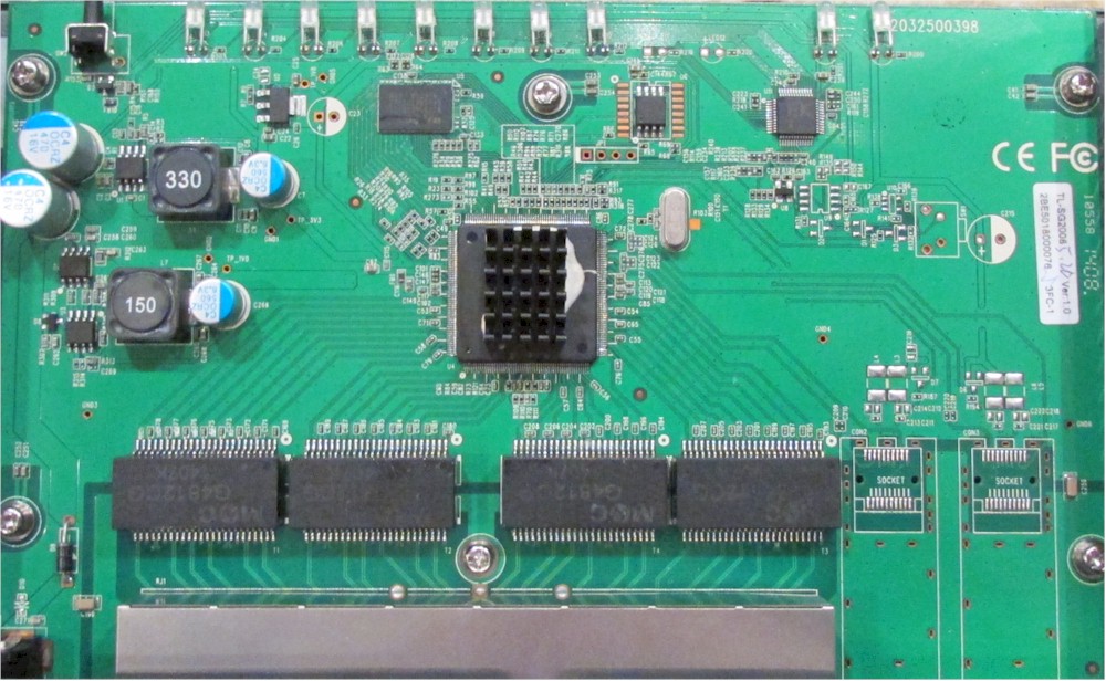
I see what I'm 95 % sure to be an SPI flash and the serial console pin holes just southwest of it.
1 Like
Did anyone check yet, what does performance of the RTL838x look like in an edge router scenario? I'm mostly interested in QoS/SQM performance limits, and whether it makes sense to integrate routing an 100/40 uplink with the switch (which would be really handy) or still go with an external router.
I have not done any tests so far in that scenario. Things like QoS can be offloaded to the switch, but there is no support presently for this in the code. These switches have a single core MIPS at 500 to 800MHz, so probably not what you would want as a VPN server, the rest needs testing.