Support for RTL838x based managed switches

This is definitely a bit late, but I still believe it's better to fix it now before the very first release of this target. A number of advanced early adopters have already been bitten by the issue. There is no doubt that it will cause endless confusion for end users trying to flash an official 21.02 image without having console access.

I'll see if I get around to cook up something later today.

We should also fixup default configuration for switches with more than one mac address, storing the full range in "u-boot-env2" like the ZyXEL GS1900 does.

And the PoE package should go in. It's working very well, and is required for the PoE feature. I see no reason to keep that out of 21.02. It will just confuse and annoy users who have to jump through burning hoops for no reason at all.

4 Likes

Seriously, I have been advocating this from the beginning of Realtek switch support. And I will bring it up once more, and then never again:

If you create OpenWrt for a device, make it an OpenWrt device.

This means using the same default config and the same default packages as any other device. Even if it doesn't look like other devices, or was a different device before (as if that was a factor anyway.)

As much sense as it makes to you to have some pre-configuration that moves it closer to the device it once was, it makes your device "based on OpenWrt" rather than "running OpenWrt." Case in point: It is easier to introduce a VLAN than to remove it. It is easier to disable the default dhcp server and firewall than to recreate it if you need it. It is easier to set an interface to DHCP from the default static adress than the other way around (yes, unfortunately this actually happens on some devices/targets.)

3 Likes

I'm trying to add support for the Netgear GS308T and GS310TP, but because of the horrible default network setup I'm having difficulty determining whether the issues I'm having is related to my total misunderstanding of using tagged VLANS or if there is an issue with the actual device! I get link lights on both the switch and the connected device, but can't get a response from ping or any other service! How exactly must the connected device be configured to access the switch?

# ip link add link enp2s0 name enp2s0.100 type vlan id 100
# ip link set dev enp2s0.100 up
# ip addr add 192.168.1.10/24 dev enp2s0.100

on your client will give you full access to the management interface (well, at least if plugged into port 1), including ssh/ luci, etc.

2 Likes

Important part to note: It will only work on port 1. That's the only port where VLAN 100 is configured.

(another reason this is a bad idea: port 1 is special on the PoE powered devices like the GS108Tv3, and using it for even temporary management might be a problem if you can't easily reconfigured the PSE)

2 Likes

Late as usual, but submitted now: https://lists.openwrt.org/pipermail/openwrt-devel/2021-April/034652.html

Not tested as hard as I'd like, so I'd appreciate testers adding Tested-by. I guess support of 21.02 backporting is important too..

The resulting default config on my Netgear GS108Tv3 is:

root@OpenWrt:/# cat /etc/config/network 

config interface 'loopback'
        option ifname 'lo'
        option proto 'static'
        option ipaddr '127.0.0.1'
        option netmask '255.0.0.0'

config globals 'globals'
        option ula_prefix 'fd1a:643c:5c9c::/48'

config device 'switch'
        option name 'switch'
        option type 'bridge'
        option macaddr 'bc:a5:11:9f:e1:23'

config bridge-vlan 'lan_vlan'
        option device 'switch'
        option vlan '1'
        option ports 'lan1 lan2 lan3 lan4 lan5 lan6 lan7 lan8'

config interface 'lan'
        option ifname 'switch.1'
        option proto 'static'
        option ipaddr '192.168.1.1'
        option netmask '255.255.255.0'
        option ip6assign '60'

config device 'lan_switch_1_dev'
        option name 'switch.1'
        option macaddr 'bc:a5:11:9f:e1:23'
1 Like

Did whoever decided on this default configuration ever purchase a switch? Every switch I've ever bought has been configurable from any port! And most will pass traffic without any configuration. A switch isn't supposed to be a firewall!

1 Like

Hi,

got a decommissioned TP-Link T1600-28TS v3 which I could use for testing. Should be RTL8382M platform. Is there anything useful I can provide/do/test. Pcb pictures, uart/console log, GPIO mapping, devicetree file, ...?

Just tell me what would be a good starting point.

1 Like

I don't know if your switch uses the Realtek CLI. If it does, show tech-support board-info (IIRC) gives you an overview of the configured GPIOs. For most it doesn't say what they are used for, but at least you get an idea of what's configured as input, output, etc.

PCB pictures can also help with figuring out what auxiliary chips are on the board: RTL8231 ICs, shift registers, RAM and flash size, etc.

The T1600G-28TS has the CLI interface footprints on the mainboard but they are not populated.

PCB Images

Overview

Power supply

SFP area

Middle area


CLI area

Daughter board

Integrated circuits

Power related

3.3V supply

1.1V supply

RAM

Flash

QSGMII Phyceiver

GPIO Expander

LAN Magnetics

2 Likes

I'm impressed they implemented two serial port options (RS-232 and micro/mini-USB).

Going by pictures of the front panel, that RTL8231 appears to be driving two LEDs per port and two system LEDs. Can you tell/measure how the strapping pins are configured? I would like to see an RTL8231 used in mixed LED/GPIO mode for once, but it's probably going to be shift register mode...

Is there any GPIO expander near the SFP cages? I wonder how the I2C lines of the modules are hooked up.

The SoC seems to be below the soldered heat spreader. Are you able to access the console? What does the boot log say, which SoC it is? I have seen the 8214QF only in combination with an 8390 so far.

Ah, nice. Proper tech porn :smirk:.

2 Likes

Got you some more pictures.

Daugther board detail

Maybe you can make out the connections from the provided images of the daughter board . If you need further details I can measure connections also.

Front

Back

SFP area detail

I don't see any GPIO expander in the SFP area just the RTL8214QF.

Front

Back

Frontpanel

You are correct with the LEDs:

  • Power (lit on power)
  • System (periodic blinking)
  • 24 Port LEDS (Green for 1000 and amber for 10/100) (blink on port activity)
  • 4 for the SFP ports (Green for 1000 and amber for 100) (blink on port activity)

Console access

Regarding the console access you are talking about the 4 pin J3 footprint? The USB and RS232 lines all seem to terminate in the unpouplated footprints at the usb controller and RS232 transceiver respectively?
If you could confirm a UART pinout I can hook up a converter and record the bootlog to confirm the used SoC.

The uart pinout is unknown, you will need to measure which pins are connected to Ground and +3.3V. Ground is easiest, use a multimeter and test continuity with e.g. the screws of the board. For 3.3V, check continuity with the 3.3V pin of the Flash chip which you can get from the datasheet (I did not check but they are basically always available), you can double-check the ground on that Flash chip. RX/TX you can figure out by trying (or check with a multimeter the pins during boot, TX usually has the higher potential). Then use a UART-USB cable and connect with 8N1 at 115200 (basically always the baud rate for the RTL-Chips, but due to the USB converter on board might be lower).

1 Like

Thanks, that is roughly what I thought. From the traces I expect top two (1,2) if arrow marks Pin1 to be RX/TX traces via vias on backside, Pin3 GND 4 traces out to ground plane, Pin4 VCC since cap and thicker passing power rail nearby. Will solder on a pinheader and confirm.

This sounds like a typical TP-Link UART header then. I can never remember the order of Rx/Tx though. Also typical of TP-Link is to not connect the Tx (and Rx) line(s), but thag can normally be solved by bridging a non-populated resistor footprint.

I can't tell for sure, but I am starting to think I want to get my hands on one of these switches too. The front-panel RTL8231 appears to be strapped in MDIO-mode, at address 0. 56 LEDs is too much to manage 1:1 via GPIO, so they must be configured as a scan matrix. Interesting!

1 Like

Indeed, this looks like:

 >1: tx
  2: rx
  3: GND
  4: Vcc

But you still need to confirm Vcc/ GND before trying those.

1 Like

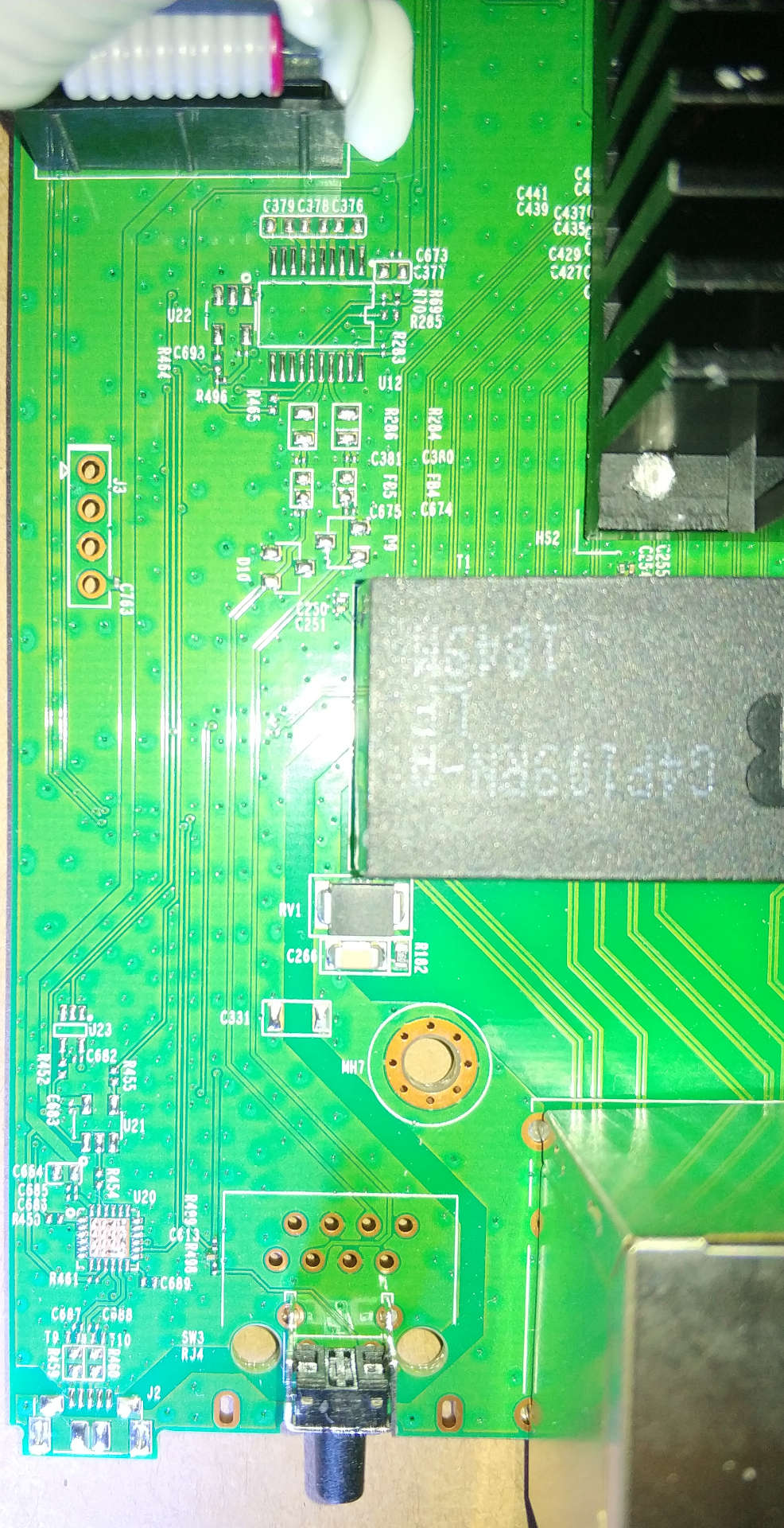
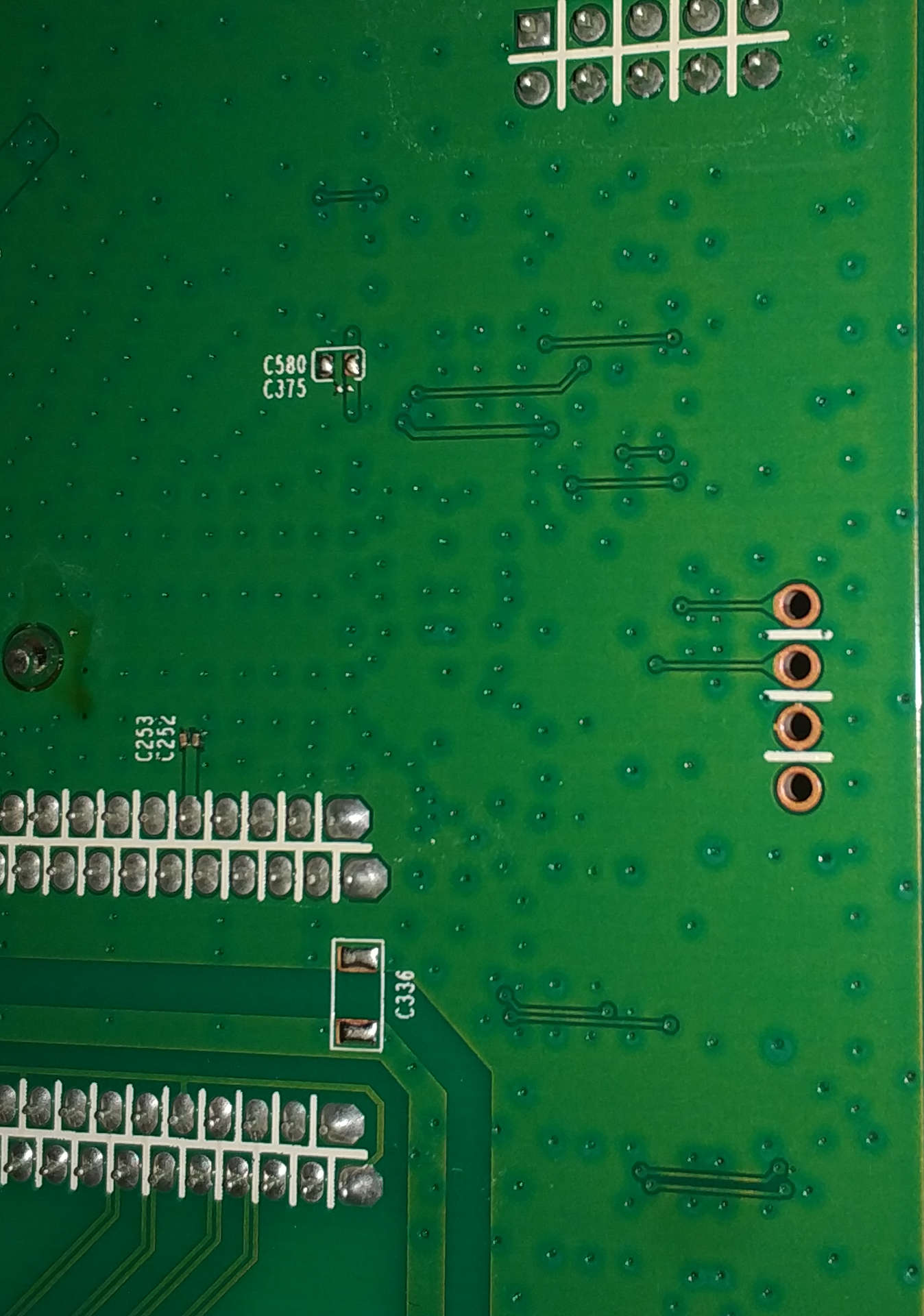
Can confirm the pinout. UART seems to be 38400 baud, 8bits, no parity, single stopbit

Hit any key to stop autoboot:  0 
                *********************************************
                *         TP-LINK  BOOTUTIL(v1.0.0)         *
                *********************************************
                Copyright (c) 2019 TP-LINK Tech. Co., Ltd    
                Create Date: Aug 14 2019 - 08:11:46

   Boot Menu
0  - Print this boot menu
1  - Reboot
2  - Reset
3  - Start
4  - Activate Backup Image
5  - Display image(s) info
6  - Password recovery

Enter your choice(0-6)

tplink> 5
Images in system:
index  Attribute  Size        Filename
-----  ---------  ----------  ---------------------
1      (b)        10485760    image1.bin           
2      (*)        10485760    image2.bin           
-----  ---------  ----------  ---------------------

(*) - with the Startup attribute
(b) - with the Backup attribute
tplink> 3

Begin to startup system, please wait a moment...

Starting kernel ...


***************** User Access Login ********************

User:admin
Password:

Note: For better protection of your network and device
please change your password firstly. Change now? [Y/N]:Y
Please enter the new password:
Please confirm new password again:
The password has been changed. Please Press ENTER.
#2006-01-01 08:00:41,[User]/5/Login the CLI by admin on console.


T1600G-28TS>

Firmware for T1600G-28TS v3 seems to be encrypted identical to T1600G-52PS v4 discussed earlier in this thread.

binwalk T1600G-28TSv3_en_3.0.6_[20200805-rel55968]_up.bin.dec

DECIMAL       HEXADECIMAL     DESCRIPTION
--------------------------------------------------------------------------------
512           0x200           Squashfs filesystem, little endian, version 4.0, compression:lzma, size: 4173556 bytes, 47 inodes, blocksize: 131072 bytes, created: 2020-08-05 07:42:00
4174336       0x3FB200        uImage header, header size: 64 bytes, header CRC: 0xF85DCDDC, created: 2020-08-05 07:41:41, image size: 3869836 bytes, Data Address: 0x80000000, Entry Point: 0x80003710, data CRC: 0xDB7329CD, OS: Linux, CPU: MIPS, image type: OS Kernel Image, compression type: gzip, image name: "3.0.0"
4174400       0x3FB240        gzip compressed data, maximum compression, has original file name: "vmlinux_org.bin", from Unix, last modified: 2020-08-05 07:41:41
8306376       0x7EBEC8        Copyright string: "Copyright (c) "
8328464       0x7F1510        CRC32 polynomial table, little endian
8354164       0x7F7974        JFFS2 filesystem, big endian

binwalk vmlinux_org.bin

DECIMAL       HEXADECIMAL     DESCRIPTION
--------------------------------------------------------------------------------
1896480       0x1CF020        Linux kernel version 2.6.32
1918384       0x1D45B0        CRC32 polynomial table, little endian
2155756       0x20E4EC        Neighborly text, "NeighborSolicits/ipv6/inet6_hashtables.c"
2155776       0x20E500        Neighborly text, "NeighborAdvertisementses.c"
2156939       0x20E98B        Neighborly text, "neighbor %.2x%.2x.%.2x:%.2x:%.2x:%.2x:%.2x:%.2x lost on port %d(%s)(%s)"
2424832       0x250000        gzip compressed data, maximum compression, from Unix, last modified: 2020-08-05 07:41:37

strings 7F7974.jffs2

+>B$'
#-TAIL-#
BgIAAACkAABSU0ExAAQAAAEAAQD7hbsK1FurprcGdQQRS1lA/shOpyZfa2mP4+kFfyLCVQi96b623eFZrg17K7Z2pS+saS3c6Hpa3+OLKSQG6237bqjcBhp9j6peKSRmabOb4H1b39SSyCFcF+tWh4wcDEafFtppq5mqd2gUtb7SRg89tbfJA7PsLkYr2rpdne2Yxg==
7C1D1FC5BF9333473D8C8052701E9BE4

I'm trying to add support for the Netgear GS308T which is similar to the GS108Tv3 but without the PD port. The firmware uses a different UIMAGE_MAGIC, but otherwise essentially no changes from the GS108Tv3. I can successfully upload OpenWrt firmware from the stock web interface and boot into OpenWrt. As far as I can tell everything appears to function properly with the uploaded initramfs kernel. I then scp the sysupgrade file to the device. I then run sysupgrade without keeping the config. The result is that after the system reboots it successfully reloads the OpenWrt firmware and gets to this point:

[    5.252514] rtl83xx-switch switch@bb000000: Link is Up - 1Gbps/Full - flow co
ntrol off
[    5.262180] /dev/root: Can't open blockdev
[    5.266896] VFS: Cannot open root device "(null)" or unknown-block(0,0): erro
r -6
[    5.275333] Please append a correct "root=" boot option; here are the availab
le partitions:
[    5.284764] 0100            4096 ram0 
[    5.284774]  (driver?)
[    5.291682] 0101            4096 ram1 
[    5.291690]  (driver?)
[    5.298660] 0102            4096 ram2 
[    5.298669]  (driver?)
[    5.305634] 0103            4096 ram3 
[    5.305642]  (driver?)
[    5.312613] 0104            4096 ram4 
[    5.312622]  (driver?)
[    5.319525] 0105            4096 ram5 
[    5.319533]  (driver?)
[    5.326442] 0106            4096 ram6 
[    5.326450]  (driver?)
[    5.333415] 0107            4096 ram7 
[    5.333424]  (driver?)
[    5.340394] 0108            4096 ram8 
[    5.340402]  (driver?)
[    5.347306] 0109            4096 ram9 
[    5.347314]  (driver?)
[    5.354280] 010a            4096 ram10 
[    5.354289]  (driver?)
[    5.361356] 010b            4096 ram11 
[    5.361365]  (driver?)
[    5.368432] 010c            4096 ram12 
[    5.368441]  (driver?)
[    5.375440] 010d            4096 ram13 
[    5.375449]  (driver?)
[    5.382454] 010e            4096 ram14 
[    5.382462]  (driver?)
[    5.389524] 010f            4096 ram15 
[    5.389533]  (driver?)
[    5.396601] 1f00             896 mtdblock0 
[    5.396609]  (driver?)
[    5.404064] 1f01              64 mtdblock1 
[    5.404072]  (driver?)
[    5.411468] 1f02              64 mtdblock2 
[    5.411476]  (driver?)
[    5.418869] 1f03            1024 mtdblock3 
[    5.418877]  (driver?)
[    5.426339] 1f04            1024 mtdblock4 
[    5.426348]  (driver?)
[    5.433809] 1f05           14848 mtdblock5 
[    5.433817]  (driver?)
[    5.441279] 1f06           14848 mtdblock6 
[    5.441287]  (driver?)
[    5.448736] Kernel panic - not syncing: VFS: Unable to mount root fs on unknown-block(0,0)
[    5.457973] Rebooting in 1 seconds..
[    6.457341] System restart.

Any clues to what might be the cause?

1 Like