Isn't it weird in a sense that its actually half-duplex and causes the reset not to actually work(Except for forcing it with GPIO-s)?
It is, those SPIF control bits have no business being in a PLL register. IIRC the issue is that one half of the connection stays in 4-byte addressing mode on reset, causing the bootloader not to load.
Sadly, there's only so much we can learn from that driver, as the interesting bits really is in the data structure (which is exactly what you said ![]() ).
).
We see that 8 sda pins (93100 has 16!!) we start with pin8 for the clock, a second clock at pin 17, so that's at least news! Could be we have clk0, dat0-7, clk1; and I would guess, any of the data pins can be connected to either clk0 or clk1; so that means the data pins have 2 mux options. But that probably needs some more digging and experimentation, and some accessible test-pads/pins to measure ...
Anyway, I've added the data to the pinout on the wiki ...
Do we know any device though that actually makes use of this? I wonder if someone has a 930x board with a big bunch of SFP cages ... I see the Enginious ECS2512 would be an interesting candidate, as would the Mestechs_MSG9424. The MS108EUP seems hard to get though as does the TL-ST1008F. But none of us on this thread seem to have any of these switches ![]() They'd be very interesting testing targets for sure.
They'd be very interesting testing targets for sure.
Yeah, I've read a bit about it, and somewhere it makes sense, it saves you on pins. I think this peripheral can be best treated as a I2C mux, such as the pca9541 and co ... at least the driver is currently already in the mux sub-dir; so that's a great start ![]()
Edit: looking more closely at the code, it claims we have 2 * 8. so the 'pins=8' is inconsistent with the writings earlier. Would not be weird to have 8 I2C data pins per controller. The i2c.h from the SDK backs this as well. I guess best idea is to request source code for the TP-Link listed above. But my gut tells me, they most likely use an RTL8231 as GPIO and bit-bang the I2C ...
Well remember, all this SoC's start their life as FPGA's. I've worked a bit with Xilinx SoC's/FPGA's and if you ever played with Vivado, it's quite obvious too, that this is how you build a modern SoC. You buy what you can as module, and glue it all together. If the module is to expensive, you usually 'borrow' something from open cores, or write your own module (in vhdl). You do some extensive tests on it, hope all your timings can be met, and then do an ASIC from it; re-test it, and if all checks out; ship it.
You can even find the define's in the code ![]() https://gitlab.com/olliver/openwrt/realtek_sdk/-/blob/openwrt-dev/bin/sdk_release.sh#L206 for example
https://gitlab.com/olliver/openwrt/realtek_sdk/-/blob/openwrt-dev/bin/sdk_release.sh#L206 for example ![]()
the GPIO is the most basic 'peripheral' a FPGA would have. It really is just a pin; and even in vivado, that's an 'open-source' module, no secrets there (as it is so trivial). Watchdog siilar, or using something off-the-shelf should be cheap.
These special bits, is where things become interesting. The switch-core, is most likely the same recycled VHDL they've been using and improve for decades. It's almost as easy as 'drag-n-drop' ![]()
Even their own internal PRL (preloader) won't load? I know there's a register that tells you the strapping bits, and the strapping bits include a pin to set 3 or 4 pin mode. If this would be miss-configured (resistor missing/incorrectly placed), then something probably goes wrong. If it is because on shutdown its set wrongfully somewhere, then it's a fixable software bug. A proper bootloader, should always be able to do the right thing (tm). But that's much further future work ![]()
I get that everything starts in simulation, moves on to real FPGA, and eventually gets onto a wafer.
Only did some basic FPGA work before I dropped out of college, but it was just a simple Spartan-6 board and no Vivado as Vivado did not support anything before Spartan-7.
I dont think that the bootloader gets stuck, as this has to happen before it, it's probably that HW fails to memory map the NOR due to incorrect addressing.
SparX-5 that I am working on has no FW blobs at all (This is a miracle with ARMv8 and A53) and the HW SPI controller memory maps the NOR, but the addressing is configurable in a register(Defaults to 3 bytes obviously) and that is how it boots as it only support booting from 0x0 of CS0 and only SPI-NOR.
I doubt anything is done in pure simulation anymore. Yes you need to still simulate a lot, but having an FPGA to run your build on happens 'in parallel' I'd argue for the non-critical stuff. I2C, GPIO, SPI etc etc. Even DDR probably, and they likely have a demo board which has some of these things (flash, ddr).
Before Vivado, there was Xilinx ISE 'web-pack' or something? I've actually used that too ![]() but that was years ago ...
but that was years ago ...
I really would like to learn more about this. I've seen some posts in this thread years ago ...
I know that as mentioned before, we have the strapping pin. Also, the BOOTROM (burnt into the SoC) in the end is also just software, so should be able to read those strapping pins and do the right thing. But, lazy devs are lazy devs ![]()
There's always 'something' burnt into the chip, unless they magically map the NOR to 0x00000) the starting address, which is super unlikely ... the ALU will need to execute SOMEthing, and that something must be at 0x0000 (or whatever they made their init address) Usually, this is where the BOOTROM lives.
Speaking of bootloader, my shameless plug:
U-Boot for XGS12xx switches (and others based on realtek rtl930x) for those that would like to help (testing) with an XGS1xxx device, please please do ![]() but lets keep discussion in that thread
but lets keep discussion in that thread ![]()
1 Like
Yeah, it was ISE Webpack, what a horrible piece of SW was that.
You are correct, they are mapping the CS0 NOR to 0x0 on SparX-5:
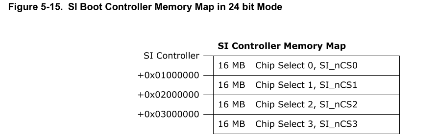
It boots in 24 bit mode for 3 byte addressing by default.
You can switch it to 32bit addressing and access up to 1G directly as MMIO.
I have asked, they claim there is not BootROM at all
2 Likes
That's interesting, but I suppose only possible for devices that 'only' support mapped storage. E.g. NAND controllers need quite a bit of setup to get all parameters right, forget about USB and UART isn't useful. If you want to be able to have 'fallback' behavior, you need a BOOTROM. BTW, your memory map is not clear if it is offset to 0x0000 (reset vector) of if there is SOME offset (SI) and those chips start at +1, +2, +3. If you know how it is mapped after boot I suppose you'll know.
The OMAP2 from TI has an interesting bootrom, in that it actually features support for all of the above, but also ethernet (DHCP + tftp) boot support. For factory control, that's really cool; as you take an empty board, and force it to netboot to provision it ![]()
I personally really like this approach much much more, no room for exploits inside the chip; no GPL violations even possible within the CHIP, no proprietary behavior inside the chip.
I wonder if our chip internally maps the QSPI also. Though I think it has NAND boot support too; but there's strapping pins for that. So maybe it also is BootROM less. MUCH less need on fixed-function devices like these. To bad we don't have the datasheet that shares with us this information, but the fact that the flash is exposed on 0xb4000000 makes me think no. I'll try to look at the address space again, and where MIPS puts its reset vector by default, that should give us some hints.
Edit: According to wikipedia for mips, the reset vector is normally at virtual address 0xBFC00000. Interesting, and I'm sure this can be changed when 'compiling'. Learned something new, that it is not always at 0x0000 ![]()
1 Like
Yes, SparX-5 is unique that it only support booting from SPI-NOR as rhat is simplest, I checked the memory map and yes, NOR CS0 is mapped at 0x0 and the rest are offset by 16MB if 3B addressing is used.
There is no NAND or eMMC booting support, nor any built-in recovery, there is literaly no burned in SW/BootROM.
Everything is set-up by U-boot, first you only have 64K of SRAM to use before DRAM is trained and you configure the console.
While this is great, means that you have to use an external programmer if U-boot gets broken.
Personally, I would have liked an BootROM like Marvells that allows recovery at least via UART.
To me it looks like RTL is also memory mapping the NOR
1 Like
It does, to 0xb4000000, but not the reset vector sadly it seems.
Very true, however, you'd still need to know HOW to send data, the protocol; and most vendors don't give this up, or have weird tooling that you'd need to use. But yes, having a fallaback to UART would be great. Putting the pinout for a socket or something similar and just use that during development would be greater ![]()
I am lucky that this is a dev board and there is dedicates flash programming connector so I just hooked up an FT232 breakout and used flashrom.
They connected the system reset to the MCP2211 that is used for UART, so I can toggle the system reset via its GPIO.
BTW, just check the frequency that it used to load from NOR, and its 20-30kHz when it starts loading.
Marvells Armada 7k and later BootROM is quite simple, you spam it with an escape sequence on boot and then just send the image using xmodem that gets booted after loading
Hi Janh,
Excellent work! I'm trying this on a hpe_1920-24g and I can't seem to get the initramfs to fully boot. It looks like the HPE bootware tries to boot it but then it stops and the regular boot process begins. This is what I see when I'm in console.
[   17.508437] rtl83xx_mdio_probe port -1 has SDS
[   17.523257] rtl83xx_mdio_probe found port 23
[   17.537506] rtl83xx_mdio_probe port 23 has phandle
[   17.553460] rtl83xx_mdio_probe port -1 has SDS
[   17.568277] rtl83xx_mdio_probe found port 24
[   17.582527] rtl83xx_mdio_probe port 24 has phandle
[   17.598486] rtl83xx_mdio_probe port -1 has SDS
[   17.613303] rtl83xx_mdio_probe found port 25
[   17.627550] rtl83xx_mdio_probe port 25 has phandle
[   17.643504] rtl83xx_mdio_probe port -1 has SDS
[   17.658321] rtl83xx_mdio_probe found port 26
System is starting...
Press Ctrl+D to access BASIC-BOOTWARE MENU
Booting Normal Extend BootWare
The Extend BootWare is self-decompressing......................Done!
Any insight on what settings I need to change to have the initramfs fully boot? Thanks for the great work!
This looks like another case of the watchdog being triggered because the ping worker doesn't get a chance to run. I guess the likelihood of this specific issue increases with the number of ports, as I am sporadically seeing the same issue on a 1920-48G. Unfortunately, I haven't found a solution yet.
1 Like
Could you hog GPIO0 to an input? That should float the WDI line for the PT7A7514, which would just disable the external watchdog.
1 Like
I already tried that, and it doesn't work (the watchdog gets triggered). And as the external watchdog is needed to reliably reboot these devices, just leaving GPIO0 in the default "blinking" state is also not an option.
1 Like
Usually, you can instruct the watchdog with how long it should wait for pings. Have we reached the max in our watchdog driver?
https://github.com/torvalds/linux/blob/master/drivers/watchdog/realtek_otto_wdt.c#L9 indicates we should be able to increase the timeout.
There is at least one kernel parameter that you could try from u-boot (bootargs): open_timeout though I'm not familiar with that one, it seems like this tells the kernel, to wait until X seconds before someone opens /dev/watchdogN to actually ping the watchdog. So setting this to 30s is not horrible.
BUT I do not know if our kernel driver actually supports this feature. Reason I say this, is that if U-Boot turns on the watchdog and sends its final ping before jumping to the kernel; the timer starts to expire, so this setting doesn't do anything in this case, because the timer is already running. If our current bootloader doesn't turn on and ping the watchdog however, we'd be good (though bad design, you want to enable the wdt as early as possible to ensure you do not get stuck hardware ![]()
In a previous project, I used an OMAP, which had an additional flag (should all really be standard required flags imo ...) timer_margin set to something nice and big; so that the kernel would load up and (re)configure the wdt, which probably/would trigger a ping (good). Might need early_enable to make sure the kernel actually loads and enables the wdt though.
I don't see any docs for out wdt, so I suppose we only support the basics; but this would be a fix. But then, I have no idea how all our platforms do their resets and if it is even tied at all to our wdt ![]()
1 Like
In this case, there is an external watchdog (PT7A7514) which is non-configurable. It has a fixed timeout of 1.6 seconds (typical, min 1.2 s, max 2.25 s).
1 Like
After adding a call to cond_resched at the beginning of the for_each_node_by_name loop in rtl83xx_mdio_probe I haven't seen the issue again.
Interestingly, that loop only takes 2+ seconds because of the pr_info calls. If I remove them, the entire loop finishes practically instantly.
1 Like
Sounds like a good reason for a patch, at least demoting some things to pr_debug() (or better still: dev_debug()). Anyone who wants to debug something, will probably have to build their own images anyway.
1 Like
Maybe the internal pull-down on GPIO0 is to blame for that. Probably still leaking enough current for WDI to sense it. Would explain why I've seen that watchdog chip with an external tri-state buffer on other boards.
The pictures of the 1920-8G don't seem to have much more than some passives around the watchdog chip (U7).
1 Like