will reveal label mac address in ascii format at 0xffe8 and wifi mac address (incremented by 2) at 0xffd4.
Not sure how to deal with 5G in rampis though, besides hadn't really tested the mac assignment in the vendor firmware
mtd1 is not uboot-env but the vendors settings, so it should probably remain nvram.
By the way, I'm using a different TLL dongle, now I can actually enter uboot... So we really don't have different devices, just my faulty dongle... sorry for that
I'll push changes soon, just trying to figure out why the factory image generation is not yet working as intended...
So... current state: I have no interfaces besides loopback... no boot led blinking pattern (probably messed up my pinmux settings if the led binding works for you?)
Maybe I find a little more time for testing at the weekend...
But at least the factory image generation is working It can be flashed via the D-Link Web UI and will detect the kernel and rootfs partitions automatically.
Did you build and flash a factory/sysupgrade image, or is this from initramfs? (You should also see a kernel panic later if the rootfs could not be mounted).
Looks like a good idea if there's a driver package for this phy
I used initramfs, regarding the driver this is exactly the driver for RTL8211E but it need to be restarted through GPIO after boot I still didn't find the what gpio ca be used and also for the buttons using the test for GPIO it doesn't detect them.
Regarding ethernet similar device: Support for Edimax EW-7476RPC
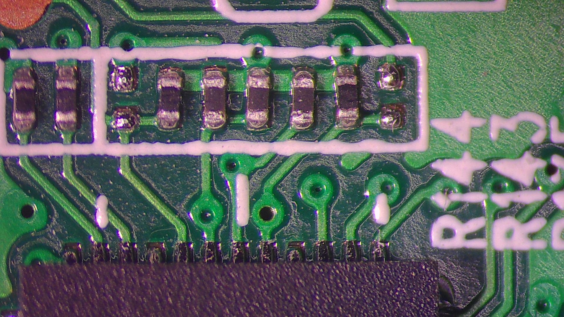
It's the pin of the unpopulated resistor in the bottom right corner of the silk-screened frame;
this is the level of PHYRSTB, which is high for my device (i.e. RTL8211E not in reset state), so this should not be the issue
However it is also connected to a via which has no connection on the bottom layer of the pcb, thus the trace vanishes somewhere into the intermediate layers, most probably connected to the SoC.
Since you defined several GPIOs for testing, maybe this is pulled to GND, so the phy would not leave reset state?
I'm trying to build with the kmod-phy-realtek package included now.
// Edit: weird, I simply don't have any interface configured after a fresh install, I can set ifconfig eth0 up, wlan0 up and wlan1 up without seeing errors, but uci show network just shows entries for the loopback adapter!?
Just pushed changes, LEDs not working, probably belong to &gpio0 or &gpio1.
The ramips target is weird, I'll better just stick with ath79 for now
I have also ath79 but this one it's small and I use it as portable if I could find USB pins that I can use it would be even better.
voltage for the resistors is 3.2v
why initramfs doesn't mount rootfs, it should be like this ? regarding the GPIO I can turn them manually but don't understand why dts isn't working
my uci show network:
und uci show wireless gives 2 wireless interfaces.
I'm using now as a repeated and it works fine. now need to find the way to enable leds and ethernet
strange that ethernet shoes connected but no traffic through it , I think it needs to be reseted.
some logs that I have for ethernet:
[ 57.233150] mtk_soc_eth 10100000.ethernet eth0: port 5 link up (1000Mbps/Full duplex)
[ 57.263863] 8021q: adding VLAN 0 to HW filter on device eth0
[ 57.408142] br-lan: port 1(eth0) entered blocking state
[ 57.418582] br-lan: port 1(eth0) entered disabled state
[ 57.429417] device eth0 entered promiscuous mode
[ 57.494727] br-lan: port 1(eth0) entered blocking state
[ 57.505212] br-lan: port 1(eth0) entered forwarding state
[ 58.252144] IPv6: ADDRCONF(NETDEV_CHANGE): br-lan: link becomes ready
[ 91.429083] done.
but still not working.
and for GPIO correct config:
initramfs will extract, as the name suggests, ist own rootfs to a ramdisk and mount that (similar to booting a ubuntu live image from a USB drive), without touching the flash.
This is particularly useful when adding support for a new device, when the flash layout is not yet known.
If you don't see the sysupgrade or factory image being created, it might be dropped due to its size exceeding the firmware partition from the dts (run make V=s for debug output to see if that happened).
So the interfaces are looking good, it's just a problem with my build then.
MT7620 has several gpio nodes, OpenWRT will map them all together into a logical numeric space. Could you post the output of ls /sys/class/gpio? There should be several gpiochip directories in there, where you could cat base to see the offset where gpio 0 of that bank is mapped to in OpenWRT.
So in the dts, I think the numbers could not be as high as 40, you most probably have to subtract the base first and specifiy which node they belong to (40 should imho result in gpio 0 of &gpio2, but again, I'm also not quite familiar with ramips).
Ethernet link but no traffic could also be due to a GMAC PLL mismatch (clock Speed on rgmii interface), but no idea how set this in ramips Does it work when putting a 10/100M Switch in between (or setting the link speed manually on the computer)?
Have you checked this is the correct gpio for DAP-1620?
When toggling the pin, the voltage change should be visible at resistors R150/R152, but you have to remove the phy-reset-gpios declaration from the dts first (can't export the gpio when it's occupied by some other kernel driver).
It seems something in the kernel is still blocking access to that GPIO (as well as many others; I was only able to test maybe around 10-20 pins out of 72), maybe the pinmux settings for rgmii, if the reset line itself could be considered part of the rgmii interface
What happens when you plug in a network cable, e.g. when connecting to a switch, will the switch LED light up, indicating any link status? Could you test with a 10/100M switch, sometimes there's a PLL clock issue with the GMAC... also still looking for ways to solve this in ath79
Not sure if it's worth trying to mess with GPIO registers manually; pinmux is called GPIOMODE in the programming manual (p. 37)
To change register values you need to select the utility io in menuconfig as well as enable the /dev/mem device in global build options -> kernel options or something like that...
did you try GPIO for the buttons ? I think as you told some of them are locked as a repeater without ethernet it was working for a day with max speed stable.
 It can be flashed via the D-Link Web UI and will detect the kernel and rootfs partitions automatically.