[SOLVED] Bricked my router, next steps

Hey all! So I accidentally killed my Archer C2 AC750 v1 yesterday. Surprise, surprise, you can't actually flash the original firmware through LuCI and have it overwrite OpenWrt, it just dosn't work that way. Lesson learned, a pretty stupid lesson, and yes, I'm paying for it by having no Internet access for the week, which might actually be a good thing. (I guess my phone's LTE modem will have to work twice as hard now.)

The router boots up with the power LED and the Ethernet LED, then the Ethernet LED turns off and the power LED stays on. The router is currently a dumb switch, which I found out by accident because I wondered why I was still getting a DHCP IP address when the router was dead. Turns out, our ISP modem also hands out DHCP reservations... so the WAN port on the router is really just a LAN port now. (And yes, I know, we're double-NATted, no way to fix that. That's a CGNAT, we've tried negotiating with the ISP, the modem is actually cemented into the wall so we can't change anything, yada yada.) Anyway, back to the topic. The web interface is inaccessible (of course) - it loads for like 2 minutes before timing out. SSH does not work. When I try booting into TFTP by holding the "WPS/Reset" button while turning on the router, the WPS "Lock" icon LED doesn't show up, which indicates even the TFTP function of the bootloader is gone. (So the entire bootloader is missing... yay.)

So... next steps. I ordered a serial-to-USB board (supporting both 3V3 and 5V because I don't know what this router uses), a CH341A programmer in case the serial headers do not work (which is likely because I think the bootloader has been nuked) and a SOP8 clip. Oh, and also a replacement router because I'm pretty sure this router is reaching EOL and it's been unstable for quite some time now - the Wi-Fi keeps cutting out, etc. I think I'll just use this router as a test bench for OpenWrt development.

Thing is, I'm not sure what to flash when I get the programming kit this week. I don't know what tools to use, I don't know what portion of the image I should use. I'm assuming I can't flash the entire bin file and call it a day, right? Like, the programmer's only supposed to flash the U-Boot partition?

Here's the output of binwalking on the original firmware (Archer_C2v1_0.9.1_5.0_up_boot(170221)_2017-02-21_17.14.36.bin):

Erics-MacBook-Pro:ArcherC2(KR)_V1_170221 ideaman924$ binwalk Archer_C2v1_0.9.1_5.0_up_boot\(170221\)_2017-02-21_17.14.36.bin

DECIMAL       HEXADECIMAL     DESCRIPTION
--------------------------------------------------------------------------------
95648         0x175A0         U-Boot version string, "U-Boot 1.1.3 (Aug 31 2015 - 16:32:16)"
132096        0x20400         LZMA compressed data, properties: 0x5D, dictionary size: 8388608 bytes, uncompressed size: 3523636 bytes
1442304       0x160200        Squashfs filesystem, little endian, version 4.0, compression:xz, size: 5317117 bytes, 649 inodes, blocksize: 131072 bytes, created: 2017-02-21 07:24:58

Erics-MacBook-Pro:ArcherC2(KR)_V1_170221 ideaman924$

So do I get the U-Boot partition from 95648~132095 bytes, and then flash that using the programmer? Or do I flash the entire image? I heard TP-Link firmware have 512 bytes as the header. Should I remove that before flashing?

Also, what tools do I need to flash? I heard if I have a Linux machine I can just use Flashrom. But what about Windows or macOS? What tools do I need to check serial? I heard on Windows I can just plug in the USB-to-serial and then use PuTTY, but what about macOS or Linux?

I know these are really beginner questions and I'm sorry if this has already been asked before. But I can't figure out the definitive answer through Googling. Will appreciate any solid advice or answers. Thanks!

screen /dev/ttyUSB0 115200

or the like works well for me. Path will be different on macOS.

tftpd-hpa is the TFTP client I use on Debian. macOS has its own built in, see https://openwrt.org/docs/guide-user/troubleshooting/tftpserver#on_mac_osx for details.

Thanks! I'll try interfacing with the serial headers when the board comes.

Do you think I might be able to get away with just threading jumper cables through the board header holes? I do have a soldering station but the pins of the jumper cables sit snug in the holes, and since I'm not flashing anything through serial I don't see the danger of a broken connection. Bad idea?

A pin header and leads works well in many cases where interruption isn't more than an annoyance. (Yes, if you're flashing over serial, solder or other robust connection is required.)

I'd continue with trying to enter push-button tftp recovery in the mean time (vary the timing of the button presses slightly), while watching the traffic with wireshark (or alternative packet loggers) - perhaps you get it working. I don't know if the c2 is supposed to support push-button tftp recovery, as there is no wiki page and no relevant information in the commit adding support for it, but if it's supposed to come with push-button tftp, but can't be recovered that way anymore, it wouldn't be very likely that serial console access would help either (still worth a try). The next potential option would be (unsoldering and-) reflashing the spi-nor flash in an external writer (still won't help you with ART, see below - probably not economically viable either).

But even if you are able to recover the device back into bootable condition, you have most likely opverwritten your WLAN calibration data (ART) - if that is the case, your WLAN would be shot permanently.

I would take the memory off the board (or clip to it if no soldering station available) and write partition by partition, then verify and put it back on. That is the fastest.
Original partition layout should be in the original boot-log.
The programmer is cheap and flashing software is OS dependent.
On Win10 I used CH341 programer
Had to fix the flasher since it was providing 5v outputs and I had a 3.3v IC.
You can do cutting and stripping with winhex.
If you have only used LuCi to try going back to stock - the boot-loader is likely ok, and the unit does not boot since there is no kernel at the start of the stock image you flashed replacing the firmware partition. You can still flash it using u-boot cli without taking the IC off.
In case ART partition was overwritten -it does not mean the WLAN is completely dead, since it contains calibration data and board parameters you can restore someone else's ART partition (same router model and hardware) replacing only the mac address you will likely have some functionality restored with it. Calibration will be lost.
Prior to tinkering I would recommend to dump the whole flash so you can dig in it later to find useful stuff such as original calibration data etc...

Holy crap, why didn't I know this? The wiki didn't have any documentation on this. If I knew that data was there and how important it was I would've backed it up as soon as I flashed OpenWrt. Hopefully that partition is intact or else this router is good for nothing.

Sorry, is this the log you get when you boot with serial?

I actually made a bit of a mistake - when LuCI finished flashing it was in a semi-bricked state. I tried the same procedure with TFTP and bricked it completely. In hindsight I should've gone back to OpenWrt first and then tried again... but you don't learn without making mistakes.

I hope it's recoverable with the serial only :confused:

Thanks for the software recommendation!

Yes, found this one on the device page on the forums. Don’t quote me on that as it is not mine... the layout is lines 158~165. Format is start/end address.

If you did something with tftp and the boot-loader is damaged you will have to use spi flashing tool 100%. It sounds harder than it actually is. Get a clip if you are afraid of soldering.

The easiest is asking someone with the same device to dump their whole flash image and then write it onto yours.

Otherwise, extract u-boot, kernel and firmware partitions from the vendor image, create a snapshot of yours overwriting respective addresses with the extracted partitions and then write it to your flash. If wireless will refuse to work, ask someone to send you their dump of memory starting from 0x0000007c0000 until 0x000000800000, overwrite it in your cooked image and flash again.

For QCA/ Atheros devices, ART is individual to each device (or at least very small batches of devices) - writing ART from another device might allow you to enable the WLAN again, but the result is out of spec. This is both a legal problem, but given today's WLAN standards also a technical problem, as ART contains the necessary compensation for component variances over the frequency spectrum at different temperatures. Without correct data here, interoperability (being able to connect with other devices) and performance suffer, a lot.

Agreed,
Calibration will be completely gone in that case.
Briefly looking at the log it looks like the cal-data is all the way in the end 0x0000007f0000-0x000000800000 : "radio" so it might have survived the tinkering :slight_smile:

Someone has to add a full mtd dump/restore option to LuCI and Wiki for cases such as this one. It will make return to prior-to-flashing state possible and not-that-harmful

1 Like

Unlikely, uboot (64 KB) and its firmware header (512 byte) are larger than the info partition (64 KB), so it's very likely that at least the first 512 byte of ART (radio) are overwritten. But that's something that will only become obvious once the device is back in bootable state (respectively once you have direct access with a spi flasher), knowing the implications helps to decide which further steps (beyond buying usb2serial adapter) might be viable (probably none for a 50 EUR device, if you have to buy soldering equipment, spi-flasher and soic8 clamps[0] - considering the questionable chances of success).

--
[0] all the necessary equipment will cost around 50% of the value of a brandnew device delivered to your doorstep, compared to -perhaps- 30% chances of success, less you you aren't familiar with the procedures and soldering

Agreed again, yet it might be a nice tinkering bench to learn from with a chance of reviving. Tools will stay anyway.
BTW, It is not that expensive to get flasher/TTL adapter and clip altogether.

I would also upgrade the flash to a bigger size if I have tools and can desolder it anyway, spending another 3~5$ for a larger memory chip and lightly modding the openwrt firmware snapshot to benefit from it... it is a matter of willing to learn vs just getting a networking solution.

Keep mind c2's tftp recovery is almost a trap, you need to put uboot in front of sysimage, otherwize you will hard brick the roiter because it overwrite uboot

So one thing I'm having difficulty understanding is exactly what position TFTP starts writing in. Because I supplied the original firmware file (which I shouldn't have), I'm guessing the recovery process wrote too much and damaged other partitions.

Correct me if I'm wrong here. If TFTP starts writing from 0x0 (0 bytes) that means I have a safety zone of 0x0000007f0000 (8,323,072 bytes), right? If so, I might be safe, because the file I flashed (the original firmware) is only 8,126,976 bytes. Even if TFTP starts writing from boot or kernel, I still have a lot of safety space left.

Worst case scenario, TFTP started writing from the rootfs partition (0x000000160000, 1,441,792 bytes) which means I only have a safety zone of 6,881,280 bytes. That means all my radio data is toast.

Again, these are all assumptions so feel free to correct me if I'm wrong.

Yup, they're both on the way, the programmer and the clip. One quick thing though, I heard someone mention using SOP8 clips is dangerous because power from the programmer could start leaking into the CPU and cause it to power on when it shouldn't be running, causing damage to the entire board (I heard it was because chips usually don't like power on output when there's no power on input.) Is this true? I would like to refrain from soldering if possible because I'm pretty terrible at it honestly, but I don't want to fry the entire board. Have you ever damaged a board from using these clip-ons?

Can you clarify what you mean by that?

Yup, I just binwalked the original firmware, it does have uboot in front of sysimage. I'm guessing my mistake was not stripping enough bytes from the beginning, where the TP-Link header is. Or I just messed up the image before flashing. :frowning:

1 Like

If you connect your spi leads, you also supply power through the flash footprint into the board, this does end up on the SOC/ CPU as well (although probably not enough current for normal operations; the high load migh thereby damage the flasher) - when the CPU gets power, it starts booting and starts reading from spi <-- problem, two devices trying to get exclusive access over the same flash chip.

If you know SOC and board as well as its designer, you may find the lanes to keep the SOC in reset, while using the spi flasher - if you don't, you need to remove it from the board while flashing.

The clip and powering up the cpu from the flasher is theoretically possible. In reality I would expect the periphery (which flash is) to be powered through a regulated line and only have high impedance interface from the cpu connected to it, but the line might be common to the cpu.

It is easy to check - just measure the resistance between flash VCC and... UART 3.3v for example. If it goes both ways with no resistance - you will have to desolder the ic or just lift the one vcc leg from the board.
Do not be afraid to learn, maximum you will lose otherwise useless board, right?

I do normally remove the flash before writing and do not have statistics.

If you ordered the same flasher as I did, you might want to modify it a touch for true 3.3v output like I did.
I think lifting vcc leg from the board and flashing with a clip will work just fine.

Thanks, @vov4ik_il and @slh. I'll see how it goes. I might have to rely on the clip though, I'm pretty terrible at soldering.

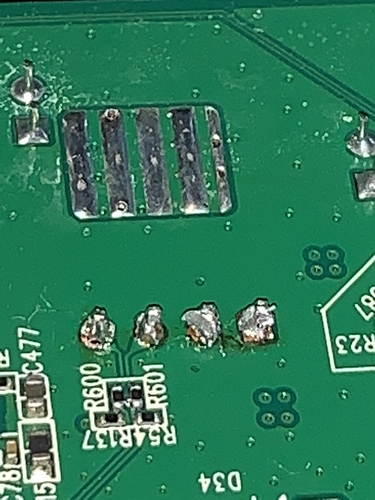
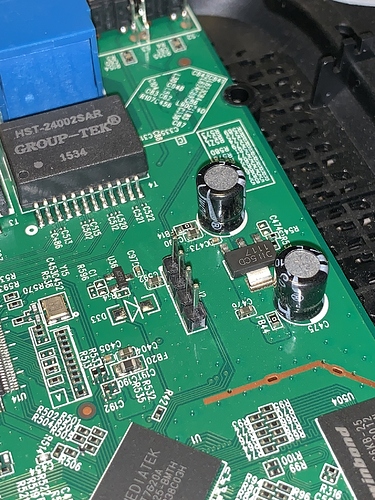
I managed to solder the header pins for serial, but it is a hack job because my soldering skills are bad. Some pictures:

Not sure if it'll actually work. Only the USB-to-TTL serial cable coming in the mail will tell. I may have actually burned the capacitors next to the headers and killed the board :frowning:.

Actually looks cold solder to me, I would give it some more heat...

3 Likes

You don't need to "cook" those connections, but a good solder joint should be smooth and shiny (with perhaps a bit of tan rosin ("crusty goo") on it. See the shiny ones near the top, one just to the left of the five bars?