As per above, i connected :
1st pin from top, Vcc : Not connected to serial
2nd pin from top TX : Serial pin 2 RX
3rd pin from top RS : Serial pin 3 TX
4th pin from top GND : Serial pin 5 GND
This is the USB to Serial convertor I am using. Remove underscore at the end.
That device is probably damaged beyond repair by now.
Just save yourself the trouble and get yourself a proper adapter and some dupont cables...
I'd highly recommend this guy, genuine FTDI (beware of fake FTDI chips (RT232R / RT232RL primarily), please don't support such actions) and very good build quality.
Cheaper device but you don't probably notice a difference if you're just doing TTL, CP2012 made by Siicon Labs and being dirt cheap it doesn't have any known fakes around (afaik).
Prolific are also around, avoid PL2303HX(D) since it's EOL and known to have lots of fakes around. PL2303TA is a more safe option but you can probably find fakes of that one too I'd guess.
CP2012/13/14 are probably the only TTL adapters (chips) I'd consider safe to get off Aliexpress if you're going that route.
Damn it, either i need Max232 IC (which i really dont want) or actual USB to TTL (which means waiting of a month). But if any of you is aware of RS232 to TTL with MAX232 IC, let me know.
I agree with all 3 of you. Damn i ordered PICKIT2 and USBASP last week but thought this shit RS232 will work :(, already it tried to f**k my laptop while i tried it for a PIC JDM Programmer, i think this should be the end of it.
My actual goal is to run this router with a USB RNDIS Wimax device. And original firmware does not seems to support RNDIS.
Anyways, many thanks all of you, i am suspending this project until i get a USB to TTL.
I would however do some research as I wouldn't be surprised if you can find fake ones around unfortunately since the chip itself seems to be around 2-3$ or so.
SPIEX is another brand that offers cheaper controllers and are probably also more "safe" as they are not as widely known...
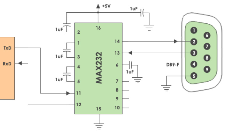
This seems to be a work around. I may retry it on PIC JDM Programmer. Lol, just seeing if it is diy doable. Damn external 5 volts and 5 extra 1uF capacitors are what is bothering me.
It's been many years since my circuity class....but...it DOES NOT appear the diagram asks you to connect a 5V supply, as the arrow is pointing OUTWARD.
It appears that there will be +5V on pin 16, and you have to attach 16 to a 1uF capacitor to pin 2 and another capacitor, and attach to Ground.
Special thanks to diizzy who pointed me in the right direction.
After a bit of patience and keeping my brain busy in other projects (Pic and AVR). I went to local store and bought MAX232 IC (It was sunday so i couldnt buy PIC ic and USBasp wasnt working for me). With the same schematics I mentioned above, IT WORKED. We can call this SOLVED.


 are what is bothering me.