Setup dumb AP with Guest Wifi network

Hi there,

I have a router running LEDE with a Guest and Master network. Now i bought a new router to extend my wifi range, also running LEDE, which i want to use as a access point, connected to the main router. They are connected using a LAN cable, and it works great for the Master network. The guest network however i could not setup.

I tried to do the same as i did on my main router, but there i have a WAN connection. In the AP i only have the LAN network. How can i setup a guest network on my AP router? The guests need to have access to the internet, but should not be able to see any device on the LAN. They do however need LAN access, because thats where the internet connection is provided through via the main router :slight_smile:

I searched for this combination, but could not find Guest on and AP mode. The idea is that the AP should serve both the "master" network and the "guest" network like the primairy router does.

Any idea how i can set this up?

I'd normally say "Search the wiki for 'dumb ap'" but its undergoing upgrades at this time.

https://openwrt.org/docs/guide-user/network/wifi/dumbap

Simplest is a wired backhaul, next easiest to set up is WDS. 802.11s is possible (as is a point-to-point link) with, for example, a Layer 2 bridge over GRE, depending on your hardware and willingness to delve into command-line configuration.

To get the kind of isolation you're asking about, you'll need a guest VLAN and a "privileged" VLAN. If using WDS, you'll need two "links" set up, one for each VLAN. VLANs run natively over Ethernet. For 802.11s or the like, you'll likely need a Layer 2 bridge; I find GRE ("gretap") the easiest to configure and it has minimal overhead.

@jeff. I've been trying to use WDS between my "main" AP and two satellite APs but it's just terribly unreliable. The link drops, or it even sometimes passes ipv4 packets and not ipv6 or other weirdness, really unacceptable.

is there a guide to setting up gretap so you can create a layer 2 tunnel between two aps over wifi? In reality I'm thinking of dropping the whole thing and running cat5e to ceiling mounted ubiquiti APs or maybe those TP-Link EAP devices, but I haven't jumped on that project yet, it's a bit of money.

I can tell you how I've configured 802.11s using VLANs and gretap tunnels over four Archer C7s.
(Note that, at present, you can't have an AP and a mesh node on the same radio)

Here's some sanitized config sections; no guarantee that they'd be operational for you, or that I've done all the IP changes properly, but it should be enough to get you at least going.

Each of the three "slave" APs establish a gretap tunnel to the "master" AP over 802.11s. Various VLANs are bound directly to the VLAN-specific pseudo-/sub-device of the tunnel end point. Watch your interface names and VLAN number lengths as if you exceed 15 characters (Linux-kernel limit) when OpenWRT automatically adds gre4t- to the UCI name, it will fail to come up.

I've shown 172.16.0 addresses for the mesh nodes so it is visually clear that they are distinct from "regular" networks. The mesh only carries tunneled traffic. My experience was that option ipaddr is required, at least for this configuration.

I've shown three VLANs; 100 is one way to configure a management interface, 200 for one with routed access, 300 for an isolated net (IoT devices).

The 10.0.0.n/24 addresses are only needed so that the boxes can retrieve opkg from outside sources.

You might want to add option delegate '0' to prevent IPv6 auto-assignment.

The firewall rules are to prevent inter-VLAN routing. My firewalls are either on FreeBSD, or use nftables, so I don't have a lot of confidence around them under UCI. Consider their presence as "you need to consider firewall rules" rather than "these are good ones".

Let me know if you've got questions, but this skeleton from the "master" AP should hopefully with get you going.

network stanzas:

# WARNING -- there is a 15-character limit on interface names
# OpenWRT adds a prefix, 'gre4t-' for example
# 'gre4t-gt201.100' is 15 characters long

config interface 'gt201'
        option proto 'gretap'
        option ipaddr '172.16.0.101'
        option peeraddr '172.16.0.201'
        option force_link '1'

config interface 'gt202'
        option proto 'gretap'
        option ipaddr '172.16.0.101'
        option peeraddr '172.16.0.202'
        option force_link '1'

config interface 'gt203'
        option proto 'gretap'
        option ipaddr '172.16.0.101'
        option peeraddr '172.16.0.203'
        option force_link '1'

config interface 'mesh'
        option type 'bridge'
        option stp '1'
        option proto 'static'
        option ipaddr '172.16.0.101'
        option netmask '255.255.255.0'

config interface 'vlan100'
        option type 'bridge'
        option stp '1'
        option ifname 'eth1.100 @gt201.100 @gt202.100 @gt203.100'
        option proto 'static'
        option ipaddr '10.0.1.101'
        option netmask '255.255.255.0'

config interface 'vlan200'
        option type 'bridge'
        option stp '1'
        option ifname 'eth0.200 @gt201.200 @gt202.200 @gt203.200'
        option proto 'static'
        option ipaddr '10.0.0.101'
        option netmask '255.255.255.0'

        option gateway '10.0.0.1'
        option dns '10.0.0.1'

config interface 'vlan300'
        option type 'bridge'
        option stp '1'
        option ifname 'eth0.300 @gt201.300 @gt202.300 @gt203.300'
        option proto 'none'
        option auto '1'

wireless stanzas:

config wifi-iface
        option device 'radio5'
        option mode 'mesh'
        option mesh_id '<your mesh ID>'
        option mesh_fwding '1'
        option encryption 'psk2+ccmp'
        option key '<your mesh key>'
        option network 'mesh'

config wifi-iface
        option device 'radio24'
        option mode 'ap'
        option ssid '<your SSID #1>'
        option key '<your key #1>'
        option encryption 'psk2+ccmp'
        option network 'vlan200'

config wifi-iface
        option device 'radio24'
        option mode 'ap'
        option ssid '<your SSID #2>'
        option encryption 'psk2+ccmp'
        option key '<your key #2>'
        option network 'vlan300'

potential firewall stanzas

config zone
        option input 'ACCEPT'
        option forward 'REJECT'
        option output 'ACCEPT'
        option name 'vlan100'
        option network 'vlan100'

config zone
        option input 'ACCEPT'
        option forward 'REJECT'
        option output 'ACCEPT'
        option name 'vlan200'
        option network 'vlan200'

config zone
        option input 'ACCEPT'
        option forward 'REJECT'
        option output 'ACCEPT'
        option name 'vlan300'
        option network 'vlan300'

config zone
        option input 'ACCEPT'
        option forward 'REJECT'
        option output 'ACCEPT'
        option name 'mesh'
        option network 'mesh'

Thanks for the replies guys, but i am still clueless :wink:

First reply about the dumpap, i read all the AP forum posts/wiki, but none mentions setting up and AP with both the private and the guest networks being exposed. Also, i had it setup with WDS, but it was very unstable and it seemed that very difficult to get the separate guest network on the AP. I then rolled out a UTP wire to the AP from my router, hoping it would be more simple :slight_smile:

From what i understand now:
Setup 2 VLANs on Router (private and guest)
Questions:
VLANs seem to be bound to eth ports. I have 1 UTP cable to my AP. What VLAN should the port be which is connected to the AP?
The guest network should be Wifi only. Will i lose 1 eth port when i setup a VLAN on one of the ports?

vlans can be bound to ports, or they can be "tagged" you'll want that cable to carry "tagged" vlans so that you can figure out which is which.

Put your main LAN on one vlan and your guest on another, both are tagged on both ends (the router end and the AP end) and then attach your guest interface to the appropriate vlan and attach your LAN to the other vlan interface.

Ok, i used this tutorial for my current guest network:
https://wiki.openwrt.org/doc/recipes/guest-wlan-webinterface

But this doesn't create to VLAN correctly right? It just creates a new interface i guess?

It looks like a pretty old "how to" based on the UI, but my quick read is that it doesn't create a VLAN and relies on the routing table to handle things.

You do that on the main router. But all that that has done is create a new network for guests that is independently routed to the Internet and can be accessed by wifi on the main router.

To extend your guest network to another AP via Ethernet, you would make the "guest" network a bridge so you can add more interfaces to it. Specifically you're going to add an Ethernet VLAN that feeds the other router (the AP). Go to the guest network edit page and on physical settings check the box for bridge. Note that the radio buttons where you attach the network to one device (the local WiFi AP) change to check boxes where you can attach to more than one device. You will be coming back to this later.

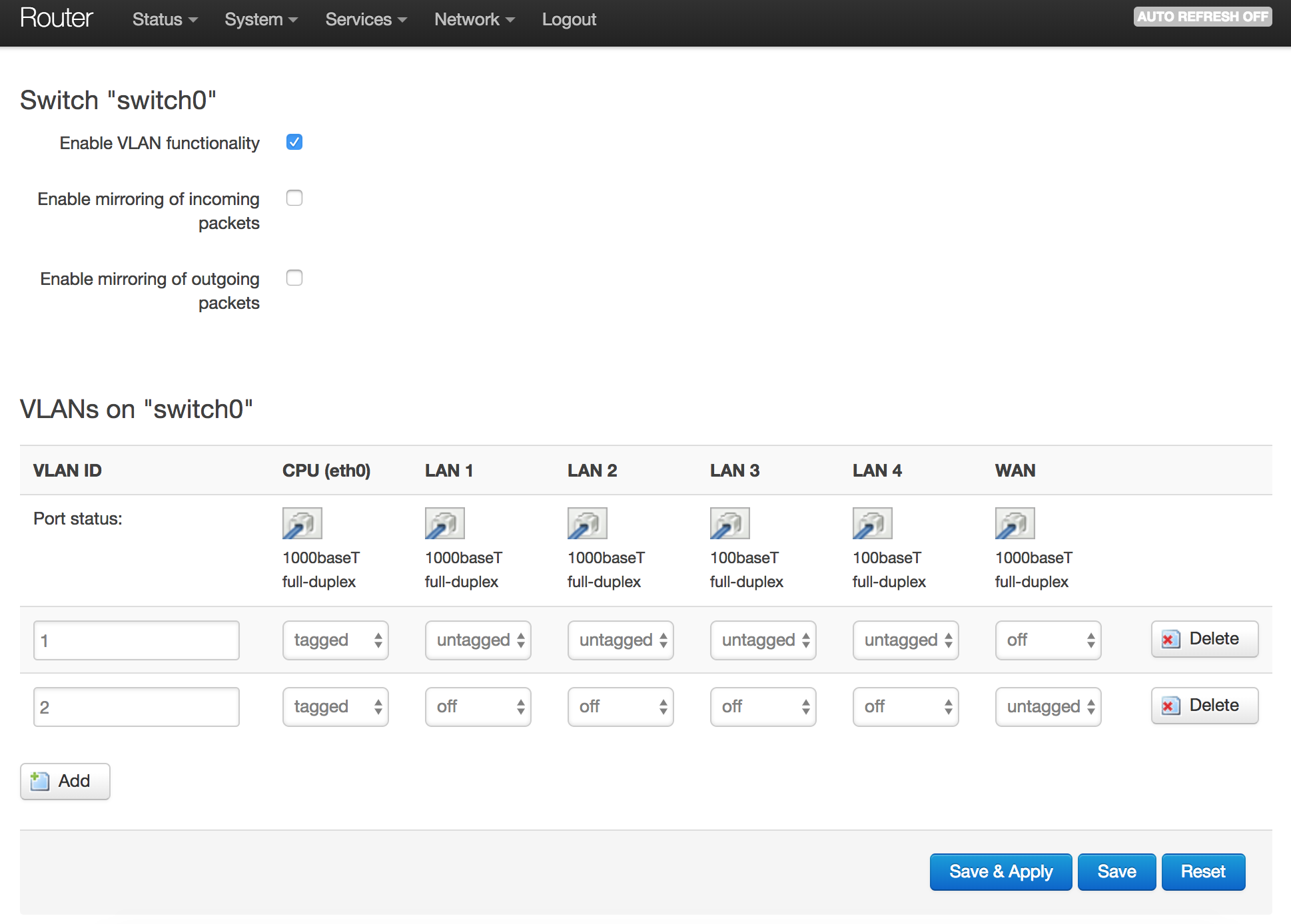
How to make Ethernet VLANs depends on the hardware you have. Unless the port is dedicated to one Ethernet cable (typically the "WAN" port on a 10/100 router), you need to set up both the CPU Ethernet port and the switch.

First, be logged into your main router on its wifi. This will have you stay connected and able to fix it if you mis-configure the Ethernet ports. On the main router you're almost certainly going to be working through a switch since the WAN port is connected to your cable or DSL modem.

On the "Network:switch" page, find the Ethernet port that is connected to the cable between the two routers. The numbering doesn't always correspond to the label on the outside of the router, so plug and unplug the cable and notice which one goes from connected to disconnected.

Make a new VLAN with the "add" button. In both the CPU and the link cable, set "tagged" on both VLANs. The other ports remain "untagged" in only the LAN VLAN, so that ordinary LAN devices like a printer can be connected.

If the default configuration of the router had everything untagged, you need to go to LAN interface edit, physical settings and change from e.g. eth0 to eth0.1, assuming the LAN VLAN is number 1 in the switch. If the LAN was already tagged in the CPU, skip this step, your LAN should continue to work without changing anything.

Usually the new "guest" VLAN is number 2, so go back to the guest interface physical settings and click the eth0.2 or eth1.2 or whatever the guest VLAN is.

You now should have two VLANs live on the interconnect port. So time to go to the remote AP. You will need to temporarily connect the interconnect cable to an untagged LAN port on the main router to have access, since the AP does not understand VLANs yet.

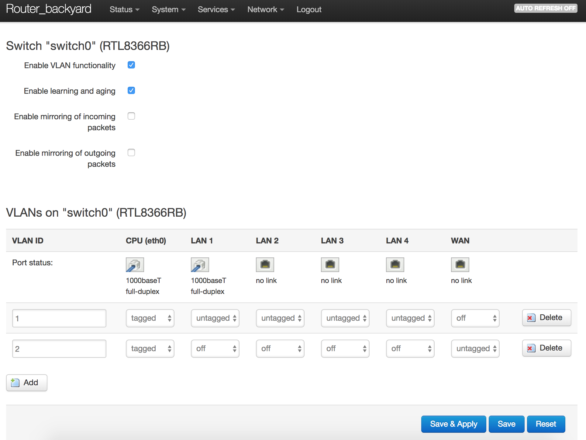
Presuming this is set up as a dumb AP with only a LAN connection, first you need to change the LAN to be tagged instead of untagged. Set up a VLAN through the switch and change the physical settings of the AP's LAN to be this tagged interface. This VLAN of course has to have the same number as the LAN one on the main router. You can now (actually you have to now) connect the interconnect cable to the tagged port on the main router, and the LAN should work as before.

Now to hook up the guests at the AP. On the AP, create a new interface called guest with protocol Unmanaged. The guests are going to be completely dumbly switched through the AP from wifi to Ethernet without the AP's CPU even looking at what they do. All the routing and firewalling of guests is done by the main router. Make it a bridge. Make a VLAN through the switch and connect that ethernet port to the guest bridge. Make a second wifi AP and connect it to the guest bridge.

If your dumb AP is a router with a dedicated CPU Ethernet to the WAN port, you don't need to set up its switch, you can just use eth0.1 and eth0.2 directly and plug the interconnect cable into the WAN port.

1 Like

Wow thnx for the huge informative reply! Fyi my main router is a TPLink Archer C7 and my AP is a TPLink WR1043ND. I dont completely understand the CPU part in your story, but maybe you know for these types?

The Archer C7 has two "real" Ethernet interfaces, eth0 and eth1. Typically one of the two is dedicated to WAN access, the other "inside" networks. It looks like the WR1043 also has two interfaces. (Some only have one, and default configuration is to use VLANs on the interface to "split" WAN and LAN.)

If you connect to "eth0.100" then that is telling the interface

  • Every packet I give you, put the "VLAN 100" tag onto
  • Only give me packets that have the "VLAN 100" tag on them

Edit:
As a suggestion, get your VLANs, SSIDs, DHCP, and all that working on the main router first. Then we can help you with either a wired, or a wireless bridge to the other unit.

A CPU ethernet port is a section of hardware that can convert data written by the CPU to a memory or I/O space directly to Ethernet packets. These packets leave the chip either to a passive transformer connected to an Ethernet cable, where signals can go 100 meters, or through a special interface called a MII which can only travel a few inches to another chip inside the router. In 10/100 routers the MII link may be only a few milimeters long to a switch section in the same chip.

Though the C7 and 1043 both have two CPU ethernet ports, both of them go MII to a separate switch chip. All the cables are driven from a separate switch chip, and there is a need to configure that chip so the packets from the CPU appear on the desired Ethernet port(s). All gigabit routers seem to be built this way because Atheros did not build a CPU chip with hardware to physically drive a gigabit Ethernet cable.

The switch is a 7 port "jungle" where anything can be connected to anything. Two of the ports are CPU ports and the other 5 are the Ethernet cables.

There are many potential ways to run this, but the default configuration is to have one CPU and four of the ethernets connected together for the LAN, and the other CPU and one of the ethernets serving as the WAN. Since there is only one VLAN connected to each CPU port, they can be left untagged. But this is a problem when you go to expand. The networks need to be reconfigured to use tagged VLANs on the CPU port.

Thank you for your support guys! However, i still couldn't make it to work. As you suggested, i am first trying to setup 2 VLANs. 1 for private use, 1 for guest use. In this screenshot you see what the default switch config of my main router is:
38

And the config of my AP is:
37

Do i need to remove the WAN VLAN? Or add a third one for guest?

Both on Router and on AP the cable is connected to the LAN 1 port.

https://blog.doenselmann.com/gaeste-wlan-auf-openwrt-access-point/
Another approach but not quite what you are asking for.

On your router, add a third vlan you can usually choose whatever number you want, but let's say 3. Then put LAN 1 port tagged in this VLAN, and also put CPU port tagged in this VLAN.

Now on your AP do the same thing.

Now on the router, create a new interface called Guest and add eth0.3 to that interface.

Now on the AP create a new "interface" called Guest, and create a new SSID/AP wifi interface, and make it a bridge, with eth0.3 and the guest wifi interface in the physical settings.

In the firewall settings of the router, let the router route guest to the wan but don't allow forwarding from guest -> lan and don't allow input from guest to router. Do the same thing in terms of not allowing forwarding or input from guest on the AP.

that should do it.

But wont this make the AP a guest only AP? The idea is to have both the router and the AP expose a "private" and "guest" wifi network.

Port 1 is untagged on Vlan 1 which is your lan, so lan packets will travel untagged between the two. Guest packets will be tagged, and so both lan and guest will travel on same wire multiplexed. Both ssids will work

It often does not work to try to run tagged and untagged packets on the same cable. Tag the LAN with VLAN1 and the guest with VLAN3.

On the AP, you would set up two wifi APs, one for LAN users and one for guests, with different SSIDs.

Thanks guys its all working now!
Like you told me, all i had to do was add a new vlan (3), tag the port which is is connected to, and set the current guest interface to bridge the guest wifi and the new vlan. Did the same on my AP and all is working now!

1 Like

Fantastic, glad it worked out so easily.