Hi @jeff does my ar150 gl.inet based on atheros soc9331 needs PHY to work ?
In normal config kernel shows loading PHY driver but in my modded one where I’ve got only the switch (SW_ONLY_MODE in openwrt/target/linux/ar71xx/image/lzma-loader/src/ar71xx_regs.h:
#define AR933X_ETH_CFG_SW_ONLY_MODE BIT(6)
Kernel dmesg doesnt says anything about PHY?

Is PHY a physical piece of equipment ?

Is it always needed ?

If always needed is it handled by switch driver in my second case (see above) ?
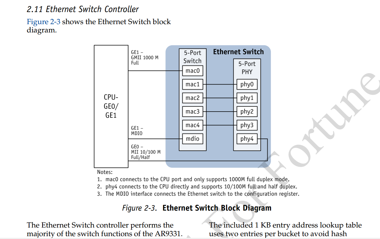
Your logs look normal. AR150 has two Ethernet interfaces, which are independent and not in the same switch.PHY4 is connected directly to the CPU through GE0
Where can I find a diagram of PHY switch GE0 in ar150 ?A more accurate one than the ar9331 soc pdf that you can find through google ?
And again
Kernel dmesg doesnt says anything about PHY?
Is PHY a physical piece of equipment ?
Is it always needed ?
If always needed is it handled by switch driver in my second case (see above) ?
An Ethernet PHY is a chip that has a physical port, i.e. it generates actual voltages that can communicate to another device via Ethernet cable.
The use of system on chips where everything is on one chip has removed that easy distinction but still the last bit of silicon to process the Ethernet signal is called the PHY. It usually has some inward facing logic to control it (turn port off and on, power saving, check status etc). When PHYs were a separate chip the standard is a slow serial link called MDIO. Failing to address and configure the PHY after power up would usually leave it not ready to communicate data.
Atheros does not release detailed information about their chips to the public.
The AR9331 Data Sheet "PRELIMINARY December 2010" can be found on the open Internet with little effort. It is a 320 page document. The version on the Internet does not bear watermarks identifying who "leaked" it, in contrast to many other QCA/Atheros documents (they often are marked with either a company or individual's name). The illustration above is from page 26 of that document. There also is an October, 2011 version as well.
As these data sheets are labeled "COMPANY CONFIDENTIAL" or "Confidential and Proprietary – Qualcomm Atheros, Inc." and may have been distributed under NDA, @Pippo would be wise to check public sources first.
problem is I did it by trial and error more than understanding the physical/logical set up
Mdio is a bus, mac is some logical link layer but should be integrated in PHY (physical device) GE0 should be an interface from CPU to PHY but is it logical over some wiring or physical the wire itself. Googling doesn’t help:
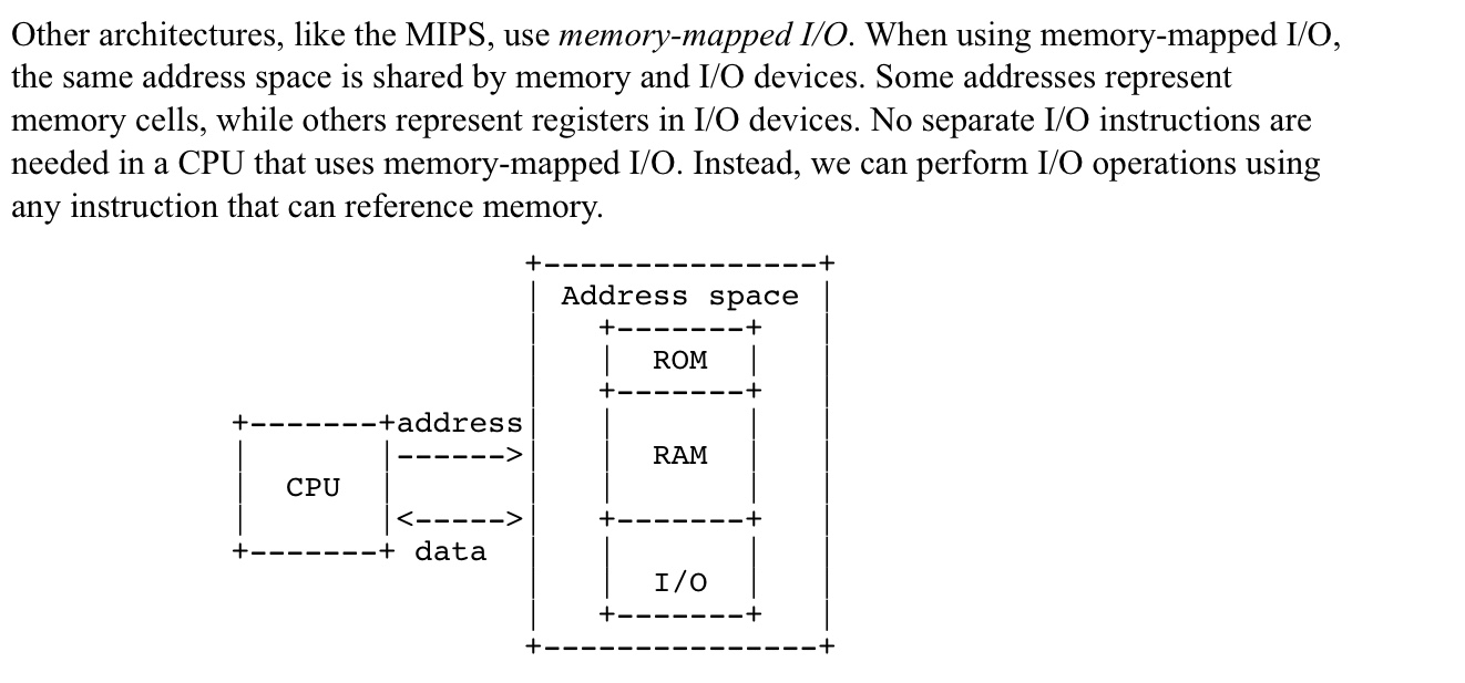
MAC - media access controller. This is the part of the system which converts a packet from the OS into a stream of bytes to be put on the wire (or fibre). Often interfaces to the host processor over something like PCI Express (for example).
PHY - physical layer - converts a stream of bytes from the MAC into signals on one or more wires or fibres.
MII - media independent interface. Just a standard set of pins between the MAC and the PHY, so that the MAC doesn't have to know or care what the physical medium is, and the PHY doesn't have to know or care how the host processor interface looks.
Probably is just because I don’t know how to read the switch block diagram ! Where to start to have a clear picture and find out how the blocks elements represent physical connection on the board ? And lastly more important why kernel doesn’t print out PHY for the modded config ? I.E. where to put some printk instruction to get it if it’s there ?
The physical connections on the board come out of the five PHY blocks. There should be lines on the diagram going off to the right to indicate that these signals leave the chip. On a pocket travel router with less than 5 Ethernet ports, some of them will not be connected to anything on the board.
The kernel can't tell which if any of the PHYs the manufacturer has connected to RJ-45 jacks. This is why each board model has different default config files and "board data" in OpenWrt.
Everything on the block diagram posted is inside the AR9341 chip, thus it can only be manipulated by software. It's shown as separate blocks but they are all inside the same chip.
Setting the switch only bit merely detaches the fifth PHY from its direct link to eth0 and converts the switch to a 6 port unit with eth1 and the five PHYs. Setting the swap PHY bit makes the special PHY with a direct link to eth0 be at the other end of the set of 5. This could be useful to simplify the board layout in a 4+1 router where the manufacturer has placed the WAN port on the wrong end of the board. In the "switch only" mode, the PHY swap would be irrelevant.
If you make a build with the "/dev/mem" kernel option enabled you can use userspace tools to poke values directly into configuration registers during run time.
I don't see what mirroring ports gains you on a three port (two PHY + CPU) box since any relevant traffic from the network is going to the CPU anyway. If you want to do fancy switch stuff you should use a better / larger switch.
Hi @mk24 thank you very much indeed for your explanation.
I'll try to dig into the
If you make a build with the "/dev/mem" kernel option enabled you can use userspace tools to poke values directly into configuration registers during run time.
I did what I did just for the sake of it and a way to prove I could do it. I know it doesnt make sense but I have a lot of spare time right now.
What I would expect reading the memory location for this bit (0x180700000 as per data sheet) ? How the switch inside the soc knows how to read this memory location or vice versa how openwrt build knows to create the memory location to store data needed by the switch chip ( I imagine there should be a switch chip inside the the soc ? Right or wrong? )